Hey all hopefully you guys can help me here..
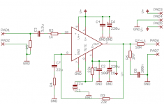
I made a PCB for a non-inverting gainclone, the circuit is exactly off the datasheet with zobel and 10ohm/inductor on output and 3.3uF dc blocking cap on the input. When I power it up off the bench supply, +/- 20v with no input or output connected, nothing happens. Once I connect the speaker (still no input) the current on the negative rail jumps to .75 Amps and continues slowing crawling up and up and up. (like around .1 amps per second) same thing happens if i have the input connected. Music does come outta the speaker if i put a signal in, and doesn't sound too bad, until the protection kicks in of course.
Any ideas?
thanks muchly guys / girls
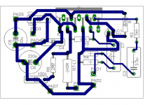
Attachments
Ok now I don't know whats up but lets see if you do ")
I fixed one amp, it has a 10k linear pot in place of R5 (no log pots in stock at the shop in town) and i replaced the input cap with a wire link. This amp works ok at low volume, but when i turn the volume up it sounds pretty terrible. I'm gonna try replacing it with a 100k log pot that I have handy, just to see if it works better.
I also have another amp, same schematic with R5 as a 22k resistor and I was just gonna use the input volume control (computer, cd player....)
This one I replaced the input cap with a wire link, but it still draws 250mA on idle (both +/- rails), and when I connect the speaker I get the same sort of behavior as when the + input was floating.
Any ideas??
Thanks again.
I have a multimeter, and I measure about 120mV on the output when i power it up, and this drops to about 60 mV after about 5 seconds. What other errors should I be checking for?
Yes, C3 has been replaced with a wire link as this was the easiest way to fix the problem with PCB.
This test was completed with nothing connected to the input.
no input/output, the bench supply shows 250mA at +/- 20V . still no input and I connect the speaker and the negative rail jumps to 1A.
Yes, C3 has been replaced with a wire link as this was the easiest way to fix the problem with PCB.
This test was completed with nothing connected to the input.
no input/output, the bench supply shows 250mA at +/- 20V . still no input and I connect the speaker and the negative rail jumps to 1A.
Oh, sorry. I apparently got the wrong impression reading your postsrayban68 said:I have a multimeter,

All this sounds fine.and I measure about 120mV on the output when i power it up, and this drops to about 60 mV after about 5 seconds. What other errors should I be checking for?
OK, just making sure . . .Yes, C3 has been replaced with a wire link as this was the easiest way to fix the problem with PCB.
Fine.This test was completed with nothing connected to the input.
Sounds right, . . .no input/output, the bench supply shows 250mA at +/- 20V ..
Now it gets spooky . . . BTW, which IC are you using?still no input and I connect the speaker and the negative rail jumps to 1A.
Ya its pretty strange, I can't understand it.
I am using the LM3886TF . I removed the chip from the pcb, stripped off the caps and put new resistors and the caps on a new board, with the old chip. Same problem. So i ripped off the chip, destroying it in the process of course, and put a new chip in (my last one ) and same problem. Next I guess I could pull off the R5 and replace it with a 10k pot, but that doesn't really answer the question.
The 250mA that it draws with no connections is not very good, it seems to me that it should be like 30mA or something... The other amp that I have draws hardly anything at all when idle.
I am using the LM3886TF . I removed the chip from the pcb, stripped off the caps and put new resistors and the caps on a new board, with the old chip. Same problem. So i ripped off the chip, destroying it in the process of course, and put a new chip in (my last one
) and same problem. Next I guess I could pull off the R5 and replace it with a 10k pot, but that doesn't really answer the question.The 250mA that it draws with no connections is not very good, it seems to me that it should be like 30mA or something... The other amp that I have draws hardly anything at all when idle.
When you bridged C3, the input cap, you made it a DC amp. Any stray DC from the preamp or whatever you drive it with is amplified. The advice given was NOT to take out C3, but to put a resistor from the +input to ground (22k was suggested). That will solve the unbalance in bias while still maintaining the AC coupling.
Be really carefull by doing random things, unless you fully understand the implications. The chip amps may be cheap, the speakers probably not.
Jan Didden
Be really carefull by doing random things, unless you fully understand the implications. The chip amps may be cheap, the speakers probably not.
Jan Didden
Yes, I was supposed to move R5, not short C3, but as it was easier to short C3 I did that instead. I figured that it wouldn't cause too many problems, since C7 ensures unity gain at DC. I also tried to connect a speaker with the input shorted and get the same results.
I will fix it properly (move R5, unshort C3) on my lunchbreak today and see if that helps at all.
I believe that R1 couples mute to -Ve and C1 to ground, as shown in the datasheet.
Thanks
I will fix it properly (move R5, unshort C3) on my lunchbreak today and see if that helps at all.
I believe that R1 couples mute to -Ve and C1 to ground, as shown in the datasheet.
Thanks
Mr. rayban, in cases like yours and in many other also, I really recommend you to read the datasheet first and all application notes before you trust an unknown website and circuit design. Start with comparing and make up your own opinion. It can be hard to understand what the datasheet says but at least there usually is a typical application and connection.
Normally you have good info there to start with and if you want you can tweak" the design.
Normally you have good info there to start with and if you want you can tweak" the design.

- Status
- This old topic is closed. If you want to reopen this topic, contact a moderator using the "Report Post" button.
- Home
- Amplifiers
- Chip Amps
- Gainclone sucking back Current