Has anybody any idea why my lm1875 gainclone lack the speed compared to the tda7375? Could it be the 2x12vac 120va trafo and 8x byv28 sharing for both channel? The sound is indeed quite good but the music tend to slow down. I follow exactly Brian Gt lm3875 based gainclonce components value on my lm1875 gainclone. Is it ok to apply the value to lm1875?
Toni.
Toni.
single supply applications require only one side of a supply...BUT u have to use at least 12V if u're aiming for +/-12V originally...split supply means u use a centre tap rafo or a dual sec trafo and produce +/- voltages...a spilt supply system will require slightly less parts...
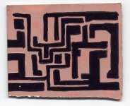
Next time I would advise you to use a different technique for your prototypes, instead of a felt pen.
Use translucid tape to cover all the copper, then carbon copy your pcb design onto it. Then use a razor blade or surgeon knife to cut the tape away following your pcb design and exposing the copper.
Then dip it in the acid.
It's quite easy and gets good looking results. It's good for just a few boards, or it will get tiresome.
Carlos
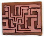
no pcb point-to-point
It ain't really a gainclone with a PCB. Try soldering directly to the chip legs. Its easy and follows the Gaincard philosophy of shortest possible signal paths...(not sure I believe that though). But anyway the making of a PCB is a roadblock you do not need with the very few components required in a minimized gainclone. Just solder!
Greg
actually i did cut the traces out with an exacto. But then just colored inside the lines. When you say to use tape do you mean leave it on while in the ferric chloride? If that works with the tape on it will be a huge timesaver. Also my pcb's are mirrored, so i must surface mount the components, not a big deal. Thanks for the help.
TDA7375 help
HI !
I would need a little help with TDA7375 chip.I plan to build an amp.
I have the chip and all the parts and the schematic is very simple.
I just dont understan, what to do with stand-by pin.I dont need stand-by function.Can I just leave the pin unconected?
I have read the datasheet but I don't understand if there should be some voltage on that pin to disable stand-by mode or is it just the opposite-apply voltage to enable stand-by function.
Any help would be welcome.
By.
Igla
- Status
- This old topic is closed. If you want to reopen this topic, contact a moderator using the "Report Post" button.
- Home
- Amplifiers
- Chip Amps
- lm1875 gainclone lack speed