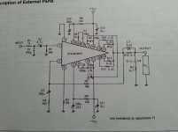
Hi all, I'm working with stk4048chips using basically the factory datasheet and I have a high pitched squeal from the tweeters with no or very low input levels (a few mv rms) above that the amps sound fine. shorted inputs also kill the squeal. On the factory datasheet it shows a zobel network 4.7r and .1uf) and also a thiele network (4.7r and 3uh) which I have implemented. My question relates to the positioning of the zobel in the circuit. Would the zobel not be more effective before the thiele network and be more effective at stopping the squealing? looking at different amp schematics most show the zobel before the thiele? any thoughts, this squealing is driving me crazy.
Would the zobel not be more effective before the thiele network and be
more effective at stopping the squealing?
Yes, certainly. The Zobel should be as closely connected to the output stage and
power ground as possible.
You are absolutely right in that the Zobel element is normally on the amplifier side of the Thiele element. However, Sanyo is Japanese and the Japanese are generally thorough with their work. Predicting how it will affect stability if you move the Zobel element before the Thiele element can be very difficult for an "outsider".
A priori I would trust the Japanese indications. Alternatively, contact Sanyo with that question and the quest will pass around in the managerial/technical hierarchy.
A priori I would trust the Japanese indications. Alternatively, contact Sanyo with that question and the quest will pass around in the managerial/technical hierarchy.
Yes, it is usual to place the RC shunt at the amp output, and the L//R network connecting to the output active terminal.
Watch out for positioning of the output coil causing magnetic coupling back into the amplifier front end (many amps place the L//R network right on the output terminal).
The input of the amp may also require loading down...can you post schematic ?.
Dan.
Watch out for positioning of the output coil causing magnetic coupling back into the amplifier front end (many amps place the L//R network right on the output terminal).
The input of the amp may also require loading down...can you post schematic ?.
Dan.
Any way to nullify overly long traces in the fb resistor?
Only good layout. The inverting node connection area should be minimized,
but the raw output signal should not be brought close to the input stage.
Several smaller resistors in series (instead of just one feedback resistor) can help,
and will also lower thermal distortion.
Last edited:
Thanks all for your responses. Any way to nullify overly long traces in the fb resistor?
You could put a small capacitor across the feedback resistor to cancel the phase shift caused by inductance.
Tyr a few picofarads to start with and see if that stabilizes your amp.
is there any certain type of resistor that the bias resistor should be...
wirewound, metal film, non inductive??
Use non-inductive wire wound types.
Which resistor do you mean by 'bias' resistor ?.All right, will hook up a cheap speaker and start fiddling, whats the worst that can happen? If something smokes i have replacement parts.Btw is there any certain type of resistor that the bias resistor should be... wirewound, metal film, non inductive??
Also, use a bulb tester while you are experimenting.
Dan.
Ok, today tried 5pf across the 56k feedback resistor...squeal still there. tried a 220pf from both sides of the feedback resistor to ground... squeal still there. in looking for 56k non inductive wire wound 1 watt resistors i'm coming up with no results from digikey mouser allied ect. do they make such a thing? So far the only way I've been able to get rid of the squeal is to short the amps input. I mistakenly thought that increasing the input caused it to go away but its still there just hiding behind the music signal. any other suggestions for the proud owner of a 5.1 oscillator thats fast losing his mind?
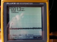
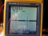
posting screen shot of amp with input shorted and amp with open input (18" rca cable) will post schematic.
I notice that the spikes are about 8.3 milliseconds apart. In frequency, about 120 Hz. I would guess they're related to the short duration that diodes in the power supply conduct. Is there a snubber network on the supply secondary? Do any of the input leads get close to the power supply?
No snubbers I have a pair of 12000uf caps right after the bridge rectifier... standard stuff... but then after the caps I have an additional pair of 6800uf caps under each amp board... connected to the 12000uf caps by 4'' wire for first two amps 8"wire for the next two and finally 12" wire to the last two. to make matters worse none of those wires are twisted. I can measure the increasing 120 hz hum as the wires to the 6800 uf caps get longer. Bad design... I now know, but fixable. so thats the 120 hz spikes but the oscillation i hear is at about 3khz also tried 5pf across the input... no change
bum squeals
The spikes may be at a 120Hz rate but the frequency content is quite a bit higher. The nice big caps get charged in short duration pulses when the transformer secondary voltage exceeds the voltage on the cap (plus the diode drop). Given their significant size I doubt that the voltage drop each half cycle is very much, so the time that the diodes conduct is short compared to 120 Hz. But the current spike is pretty significant. You might try a snubber network on the secondary before the diode bridge. I've used a 0.01uF cap in parallel with an RC consisting of 0.1uF and 180 ohms in series. See Mark Johnson's post regarding snubbers if you want to get more accurate.
The spikes may be at a 120Hz rate but the frequency content is quite a bit higher. The nice big caps get charged in short duration pulses when the transformer secondary voltage exceeds the voltage on the cap (plus the diode drop). Given their significant size I doubt that the voltage drop each half cycle is very much, so the time that the diodes conduct is short compared to 120 Hz. But the current spike is pretty significant. You might try a snubber network on the secondary before the diode bridge. I've used a 0.01uF cap in parallel with an RC consisting of 0.1uF and 180 ohms in series. See Mark Johnson's post regarding snubbers if you want to get more accurate.
- Status
- This old topic is closed. If you want to reopen this topic, contact a moderator using the "Report Post" button.
- Home
- Amplifiers
- Chip Amps
- zobel net question.