Hey people,
I often read, an inverted gc should have a preamp/ buffer at the entry. Long story short: I'm building 3 inverted LM1875 right now, and they're as good as done. Sure I've read a lot about the preamp/ buffer stuff and my HD is full with schematics.
Now I don't know which one to build. I've got a couple of NE5532 OPAmps and I'm not sure if I need a gain stage. I think a simple buffer would do the job.
I'm also confused about the often to find volume pots, which I don't need. What have I to put in as a replacement? A resistor with the highest value of the pot, the middle, or maybe nothing?
I also had to learn, that the 7815/ 7915 IC's I've got don't like more than about 18V as input voltage, so I had to ask a friend, and he gave me some real vintage stuff. Will these be ok for the preamp/ buffer psu? >
http://datasheet.digchip.com/000/000-0-RC4195N.pdf
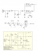
Would you eventually recommend one of circuits in the picture?
best regards J.
I often read, an inverted gc should have a preamp/ buffer at the entry. Long story short: I'm building 3 inverted LM1875 right now, and they're as good as done. Sure I've read a lot about the preamp/ buffer stuff and my HD is full with schematics.
Now I don't know which one to build. I've got a couple of NE5532 OPAmps and I'm not sure if I need a gain stage. I think a simple buffer would do the job.
I'm also confused about the often to find volume pots, which I don't need. What have I to put in as a replacement? A resistor with the highest value of the pot, the middle, or maybe nothing?
I also had to learn, that the 7815/ 7915 IC's I've got don't like more than about 18V as input voltage, so I had to ask a friend, and he gave me some real vintage stuff. Will these be ok for the preamp/ buffer psu? >
http://datasheet.digchip.com/000/000-0-RC4195N.pdf
Would you eventually recommend one of circuits in the picture?
best regards J.
Attachments
Hey J,
Let's start with the easy part:
7815 can handle up to 35V at the input. 7915 down to -35V. 1-1.5A output current depending on the manufacturer.
Your RC4195 should work but can supply only 100mA.
The reason why a "GC" (gain clone, right?) in inverting coupling is often given a buffer at the input is that the GC (in inverting coupling) often has a rather low input impedance. Typically some 1K-2K2. If you operate the GC directly from the output of a headphone amplifier, you do not need a buffer.
For the gain: from input to output you should design for 25-30 times amplification. So, if your LM1875's are set for a gain of 15 (as example), let the buffers have a gain of two. If you have a total gain of some 25-30 and a volume control somewhere else in the system, simply leave out a potentiometer (straight connection / no attenuation).
Last edited:
A pair of these, of 6, should do it. We benefit from the glut of diy led hacks. $12 for the pack of 6.
Amazon.com: eBoot 6 Pack LM2596 DC to DC Buck Converter 3.0-40V to 1.5-35V Power Supply Step Down Module: Automotive
Amazon.com: eBoot 6 Pack LM2596 DC to DC Buck Converter 3.0-40V to 1.5-35V Power Supply Step Down Module: Automotive
The first picture on the top (parallel op-amp buffer) look like my drawing in the Inverting LM1875 schematic:Another Inverting LM1875
Paralleling op-amp reduce noise and increase output current capability. Good power supply can increase sound quality. Example: Super regulator by Walt Jung and Jan Didden. I use modify Pooge regulator and it is noticeable improvement against LM317/LM337.
Paralleling op-amp reduce noise and increase output current capability. Good power supply can increase sound quality. Example: Super regulator by Walt Jung and Jan Didden. I use modify Pooge regulator and it is noticeable improvement against LM317/LM337.
Would you eventually recommend one of circuits in the picture?
best regards J.
- Status
- This old topic is closed. If you want to reopen this topic, contact a moderator using the "Report Post" button.