Hi "DIY"ers
I ve got a question today, attached is a zip file which contains schematics for PGA2310 which unfortunatley is in pdf format, with PIC16F877. My question is that does any one have the schematics and PCB layouts of this sort, or better like 5.1 application in any of the circuit designing software like Protel99Se, Circuit maker 2000 or proteus then please post it here or email me.
I'd certainly appreciate the help.
abidr, there is no published, and those files i send you should not be published before we have final results and the device is working. There is a multichannel preamp with PIC18******* and PGA2311 from elektor. As far as i know the stereo version was published in the last elektor, multichannel will follow.
You have to wait until Pieter changes the stereo version to multichannel, or take the circuit diagramm and draw a new version by yourself - you will have my guidance for this. A start would be to redraw the schematics you recived in you preferred software.
Everbody else who wants to work on it is welcome of corse.
Till:
Hi Bro: Thanks for the reply I just wanted to know if someone else has emabarked on this sort of project, for a starter I will be drawing the PCB and schematics for the stereo version, on weekend, good news is that just today recieved Protel 2004 sofware and I guess files send in by u should work in it.. will get back 2 u at ur email.
Rehan
Digital pot for 5.1
hi abidr,
have you started with your project. i am also interested in knowing how the volume is controlled. Can you control channels individually as well as together? Do you need to program the chip?
I have built a 5.1 amp and would like to experiment with the digital pot.
regds
hi abidr,
have you started with your project. i am also interested in knowing how the volume is controlled. Can you control channels individually as well as together? Do you need to program the chip?
I have built a 5.1 amp and would like to experiment with the digital pot.
regds
A stereo version of this is working with a software for controller that has not all features planned implemented yet, abidr is busy modifying the schemtatic for 6 channels instead of 2.have you started with your project.
It is controlled with a switchable resistor array in the PGA2310 / 2311i am also interested in knowing how the volume is controlled.
This only depends on software implemetation, at the moment our software is working with all channels get same volume, individual levels will follow later. The hardware does fully support this.Can you control channels individually as well as together?
someone needs to do soDo you need to program the chip?

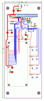
I think, till has answered all the question, I have modified the schematics, which will have to be reviewed then will come the tricky part and thats PCB layout, will be working on it on weekend as it will be a 3 days weekend, compared to noram which is 1 day back here in pakistan.
Once I m done I ll get back to the forum.
Till then keep ur fingers crossed.
Once I m done I ll get back to the forum.
Till then keep ur fingers crossed.
Hi,
you may easily parallel three PGA2310/11 and get a fice-channel-plus-sub-volume control. This can be don with the Elektor solution, Ulrich Böhmke of ub-Audio (www.ub-audio.com) sells a kit (which i have built: look at www.krishu.de > hifi > electronics > pre) and there are even more (at least in Germany) who sell or build stuff like that.
Cheers
Christian.
This is quite interesting. I've read up on the PGA2310 chip, and pretty much understand how that will work. Yay. But I'm not sure what to use as the controller chip? Would that be the PIC16F877 you mentioned? Also, you just need the one controller chip, and then as many of the PGA2310 chips as needed, correct?
Thanks!
Thanks!
You don´t need a big microcontroller like the 877 only for control of some PGAs. You need it if you want a LCD, some relays, whatever. A preview on a device with more features here: http://home.tu-clausthal.de/~tpa/space/IM002696b.jpgWould that be the PIC16F877 you mentioned?
A small MC works also: http://home.tu-clausthal.de/~tpa/PGA/index.html
Yes you can control as many PGAs with one MC as you want. How fast we will be ready to publish one like that with 6 channels depends widely how many time abidr finds to work on the layout.Also, you just need the one controller chip, and then as many of the PGA2310 chips as needed, correct
Oh wow, that's definately cool. So you need a specialized rotary encoder to connect to the MC to adjust the volume...?
So when the layout is complete, you'll post a parts list and possibly good vendors for them, I hope. Also, will you be posting the code to program the MC?
Finally, how do you go about programming the code into the MC? Do you need a specialized device to do it? And if so, how much are those?
Thanks!
So when the layout is complete, you'll post a parts list and possibly good vendors for them, I hope. Also, will you be posting the code to program the MC?
Finally, how do you go about programming the code into the MC? Do you need a specialized device to do it? And if so, how much are those?
Thanks!
no special, any with this 2 Bit grey code output will do.a specialized rotary encoder
It´s not a real problem to buy them, and in case i have 30 or 40 of them in stock...
how do you go about programming the code into the MC? Do you need a specialized device to do it? And if so, how much are those?
also no special, any ICSP PIC programmer does it. I don´t know how much they are, but you can build one diy for about 5€ parts. There are many schematics on the net like http://www.sprut.de/electronic/pic/projekte/brenner5/br5_sch.gif
Also, will you be posting the code to program the MC?
I don´t know yet what i will post, but i will write enough documentation to build the device and at least a firmware to get it working on my homepage.
Also i send out preprogrammed MCs and encoders on request. Check my homepage for information.
Multichannel PGA2310 preamp project
Hey guys,
I've recently completed a 2ch preamp on PCB with a PGA2310 with full onboard regulated PSU, input & output buffering and bandpass filters already implemented (basic idea from M Hennessy's project as I was too lazy to calculate the values myself and re-invent the wheel). It just needs an external SPI signal from a PIC and you're set. The quality is excellent, although there is a little crosstalk between the two channels (inevitable if you're using a dual device due to parasitic capacitive coupling). Its completely inaudible unless you're blasting one channel and muting the other, but only connect an amp to the muted channel. My Rotel THX surround processor has more than that so its not that bad.
It seems most people wants to try the whole rotary encoder idea which is neat because you only need a PIC with 1 input and 3 output ports. On the downside they tend to be expensive, some form of volume indicator is necessary and one needs to reference the turnon volume. Storing the last used one is good but not always practical, starting from -92.5dB is tedious.
A much better method (IMO) is to use a PIC with a built-in ADC connected to a standard lin pot for the volume. Basically you only need one port for volume adjust as well as muting. Most PICs incorporate a 10bit ADC and the PGA uses an 8bit register. The pot can therefore supply as voltage divider by connecting the wiper to the port and the other two pins to ground and Vdd any value between 0 (0V) and 1024 (5V) to the PIC. This is easy to interpret as a value between 0 and 255 of whichever gainband you like with simple arithmetic. By connecting the pot to Vdd via a resistor gives the ability to control mute with the same port, as the pot will then only supply a value between 0 and say 1000. By pressing a button connected directly to Vdd and the port will send it therefore 5V straight (1024) which can be interpreted as a mute command. There is no need to store any values in memory and a display is optional as the mechanical pot position defines the volume.
Yes you don't have such a wide variety available and it rules out the (overkill) venerable PIC16F84, but there are more than enough examples available. The PIC12F675 is a nice basic 8pin model with 5IO and one output port available, and retails for as little as $3. It has an internal 10bit ADC and 4MHz RC oscillator, so basically you need the chip, power and the pot and you're set. The PGA is not fussy at all about clock accuracy (it just shifts the data on the clock pulse) so a crystal is overkill. Using 3 ports for the PGA and one for the pot still leaves you with 2 open ports which can be multiplexed into 4 for other functions such as balance, power monitor, fan control, relay drive etc. If you really need more ports the PIC16F876 has more than enough plus internal ADC.
Anyhoo, I'm working on a top-quality version of a single channel PGA PCB (muting one channel on the PGA and using single opamps to prevent crosstalk). Its the same schematic as my current 2ch version but with optimized PCB layout, single channel use and top-quality OPA627 single opamps as buffers. Those who know about PCBs will know that it is cheaper to manufacture a few small identical boards than a single large one.
I'm planning to build 8 of them for a 7.1ch system, each with its own analog PSU. The board design so far is fairly small, about 2" x 5" each. Each one has a 5pin input connector and 5pin output connector at the digital side for Vdd,gnd,CS,SCLK and SDI/SDO, so the boards can easily be stacked with just 5pins going from the PIC to the 1st board and from there daisy-chained to the rest. A simple LED display and buttons can be used to adjust individual channel gains and the proposed ADC with a pot for master volume. At the back I will include an RJ11 socket for in-circuit programming. Power will be supplied from a 200VA transformer with 8 equal secondary +/-13V RMS taps, one set for each channel. A small separate 10VA transformer or so will be used for the PIC and PGA digital supply.
Oh well, that's the basic idea. I will post further possibilites, schematics, layouts, photos, C programming code and programming advice if there is genuine interest and people are willing to help out and not just leach info.
Pierre
OK guys its good that regular and good quality inputs are keeping this thread running, as for me I had all the plans to make six channels PCb on the weekend, unfortunatly due to voltage fluctuation my 80 gigs harddrive got busted and along everything else it will take a while to transfer backup data to new harddrive nd make a new PCB, till that time be happy.
 .the pot boards including 2 motif(pga2310 or relay array) and mounting RCA terminal on the boards.
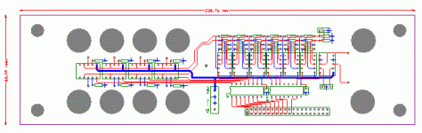

 of the sub channel, what it puts out is 6 channels...
- Status
- This old topic is closed. If you want to reopen this topic, contact a moderator using the "Report Post" button.
- Home
- Amplifiers
- Chip Amps
- 5.1 Volume control with PGA2310