How would you go about plotting an OPEN LOOP response for the LM1875
how do you make it an open loop and see?
TI has their own measurement in fig. 12 here. http://www.ti.com/lit/ds/symlink/lm1875.pdf
They have simulation models here. LM1875 20-W Audio Power Amplifier | TI.com
To make your own measurement, use a circuit like this. https://waset.org/publications/1000...loop-voltage-gain-of-an-operational-amplifier
Yeah thats where I based my simulation from.
What I wanted I guess is quite difficult. I want the open loop op amp and see how the poles affect and stuff.
But I guess I can just super impose all the low pass and high pass filter and see it from there, but that wont tell me anything about stability right?
What I wanted I guess is quite difficult. I want the open loop op amp and see how the poles affect and stuff.
But I guess I can just super impose all the low pass and high pass filter and see it from there, but that wont tell me anything about stability right?
Good catch. You'll definitely need the DC blocking cap if you're going to use a single supply.
Not necessarily. It could be a 1 kW capable sub for all we know.
I highly doubt that's modelled. Besides, the current limiter in the LM1875 doesn't shut down the chip. I just limits the peak current. Also, if the chip was actually in shutdown, it wouldn't produce 30 V on it output. It'd produce 0 V.
Tom
I believe it does model the current shutdown ish, as I change my loads it clips where it shouldnt be clipping, using 4 ohms loads oppose to 8 ohms load. The Cap was instantly fixed after posting the picture.
Transfer Function of LM1875 Feedback loop
Hi everyone, just back at it again with some hard questions that I can't answer myself.
I was hoping you guys can shine some light here.
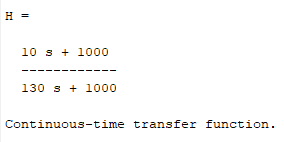
So.. I tried obtaining the transfer function of the close loop system of the LM1875 op amp with the capacitor attached to see how it affected the bode plot.
I believe I did obtain it here: I was wondering if this is even right? I assumed the input just to be VIN so nothing fancy.
Isn't this a lag controller as well?

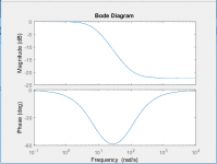
Here's the bode plot of the transfer function

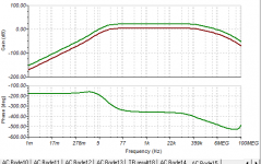
However the op-amps bode plot is this: I get it isnt the same due to not modelling it 100% however can someone tell me if I am on the right track what to look out for etc?

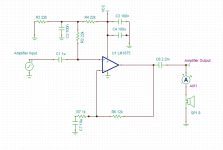
Schematic

I believe I figured out how to get the desire power, however now I want to know how to change the OP-AMPS bandwidth -- meaning how to change the frequencies it can see and amplify and I believe that is thru many LP and HP filters through the amp.
Hi everyone, just back at it again with some hard questions that I can't answer myself.
I was hoping you guys can shine some light here.
So.. I tried obtaining the transfer function of the close loop system of the LM1875 op amp with the capacitor attached to see how it affected the bode plot.
I believe I did obtain it here: I was wondering if this is even right? I assumed the input just to be VIN so nothing fancy.
Isn't this a lag controller as well?

Here's the bode plot of the transfer function

However the op-amps bode plot is this: I get it isnt the same due to not modelling it 100% however can someone tell me if I am on the right track what to look out for etc?

Schematic

I believe I figured out how to get the desire power, however now I want to know how to change the OP-AMPS bandwidth -- meaning how to change the frequencies it can see and amplify and I believe that is thru many LP and HP filters through the amp.
Last edited:
I want to know how to change the OP-AMPS bandwidth -- meaning how to change
the frequencies it can see and amplify and I believe that is thru many LP and HP filters through the amp.
The C2 value should be more like 10uF to 100uF.
The various capacitors in your schematic all reduce the LF response.
The amp IC itself, and the feedback resistor values, determine the HF response.
The circuit can be divided into 3 (more or less) independent blocks for analysis:
1) the input circuit (parts connected to the + amp input)
2) the amplifier (and feedback components connected to the - amp input)
3) the output circuit (parts connected to the amp output, which are C6 and the load).
Last edited:
How is the value of C2 picked, and the purpose?
I just see a way to shunt the AC input signal to ground.
Often a circuit component serves multiple purposes at the same time.
C2 is part of the "single supply" input biasing circuitry.
Two of the 22k resistors (R3 and R4) derive a voltage of 1/2 Vcc.
This DC biasing voltage is coupled to the + amp input via the third 22k, R2.
The C2 filters this derived biasing voltage, and also serves as an AC ground
for the top end of R2. The R2 is the circuit's midband input impedance.
The C1 capacitor AC couples the input AC voltage to the + amp input, and to R2.
C2 should be at AC ground for all input AC voltages coupled by C1.
That's why it should be much larger than C1, since it serves as a power supply ground.
Last edited:
Hmm interesting, but wouldnt it be the same thing as removing C2 and R2,
as the non inverting input will still see both the super imposed 15V and the AC signal
If C2 is removed, and if R2 is shorted, noise and ripple from Vcc
will be directly coupled into the input of the amplifier.
If C2 is removed, and if R2 is shorted, noise and ripple from Vcc
will be directly coupled into the input of the amplifier.
Isnt that what C3 and C4 should be doing?
Isnt that what C3 and C4 should be doing?
There will always be ripple and noise on the Vcc of a power amplifier
unless a huge regulator is used, which is expensive and seldom done.
Ripple on a simple capacitor input supply looks like this:
Know Your Power Supply Jargon: Ripple | AMETEK Programmable Power Blog
Last edited:
I see I see.
When designing LP and HP fillter of the op amp it isnt taken to account of the bode plot right?
its taken as face value saying oh lets just filter out Radio waves and useless frequencies correct?
One paradigm is to filter the input signal to the audio band, 20Hz-20kHz.
Another approach is wideband design, something more like 2Hz-200kHz response,
to minimize phase shift in the audio band. H-K did that back in the 60s.
Last edited:
One paradigm is to filter the input signal to the audio band, 20Hz-20kHz.
Another is wideband design, something more like 2Hz-200kHz.
HK did that back in the 60s.
Yeah I get that, but I meant in terms of the bode plot of the op amp. You can see it above. Do you have control over that or does it shift to how many LP or HP filter you integrate with the op amp?
Do you have control over that or does it shift to how many LP or HP filter you integrate with the op amp?
You can control the various poles/zeros, other than those built into the amplifier.
For those, you have to design the feedback circuit for adequate stability margin.
You have more flexibility with circuit blocks outside the nfb loop, than with those within.
See post #28.
Last edited:
You can control the various poles/zeros, other than those built into the amplifier.
For those, you have to design the feedback circuit for adequate stability margin.
ahh kk this is the last piece of the puzzle is the poles and zeroes. How does one do control theory analysis on this amp and see how you want your bode plot to look like
ahh kk this is the last piece of the puzzle is the poles and zeroes.
How does one do control theory analysis on this amp and see how you want your bode plot to look like
Yes, first you decide on the response needed. Then you try to achieve that goal
within the amplifier's limitations. The hard part is the amp IC and related nfb components,
to achieve the desired gain but still be stable at hf. Most would use the data sheet or
a simulation program for doing this. Parasitics, circuit layout, etc. should not be neglected,
even though they are not shown in the schematic.
The input circuit, and output capacitor sizing, are relatively simple.
Last edited:
- Status
- This old topic is closed. If you want to reopen this topic, contact a moderator using the "Report Post" button.
- Home
- Amplifiers
- Chip Amps
- Purpose of a feedback Capacitor (Ci)