Hi all,
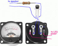
I've built an amp across an Anaview AMS 1000 module a few months ago, and now i'm planning to add a vu meter kit like this one: 2x Panel VU Meter 500UA Warm Back Light Recording&Audio Level Amp w/Driver Board 898149527904 | eBay
The intention was to connect it in parallel to the inputs but... from what i see the board has a three-pin input, L+, R+ and a common GND. Since i'm running my amp in balanced mode, i'm wondering if there's a way to drive those meters without shorting the two cold poles.
I would build a little difference amplifier on a piece of prototype board.
See here: https://www.electronics-tutorials.ws/opamp/opamp_5.html
Due to the 60 V RMS output swing of your amp module, I'd use R1 = R2 = 47 kΩ and R3 = R4 = 4.7 kΩ for a 20 dB (10x) attenuation. Do note that R1 and R2 see the full amplifier output swing, so if you run the amp to clipping, they can dissipate significant power. With the values I've given regular 1/4 W resistors will work just fine.
Also keep in mind that the input voltage of the opamp should not exceed the supply voltage, hence the 10:1 ratio in the resistor values. I'd consider adding 33 nF (ceramic or film type; nothing fancy) across R3 and R4 to limit the bandwidth of the circuit as well. This is especially important with Class D amps.
Most opamps will work in this circuit. I'd use something like the TL072 or similar inexpensive opamp. OPA2134 will work too. These are dual opamps, so you'll have enough amps for your stereo in one package.
The output of the difference amplifier goes to your VU meter circuit.
You can power the circuit from the ±17 V auxiliary supply on the amplifier module.
Tom
See here: https://www.electronics-tutorials.ws/opamp/opamp_5.html
An externally hosted image should be here but it was not working when we last tested it.
Due to the 60 V RMS output swing of your amp module, I'd use R1 = R2 = 47 kΩ and R3 = R4 = 4.7 kΩ for a 20 dB (10x) attenuation. Do note that R1 and R2 see the full amplifier output swing, so if you run the amp to clipping, they can dissipate significant power. With the values I've given regular 1/4 W resistors will work just fine.
Also keep in mind that the input voltage of the opamp should not exceed the supply voltage, hence the 10:1 ratio in the resistor values. I'd consider adding 33 nF (ceramic or film type; nothing fancy) across R3 and R4 to limit the bandwidth of the circuit as well. This is especially important with Class D amps.
Most opamps will work in this circuit. I'd use something like the TL072 or similar inexpensive opamp. OPA2134 will work too. These are dual opamps, so you'll have enough amps for your stereo in one package.
The output of the difference amplifier goes to your VU meter circuit.
You can power the circuit from the ±17 V auxiliary supply on the amplifier module.
Tom
I noticed just now that both hot and cold poles carry the entire signal (the cold at the opposite polarity). I thought that each is used only for half the signal but i was wrong since it's mirrored in the cold pole.
In light of this, it is possible to connect the VU driver board directly to the XLR inputs as follows:
HOT L - GND (one of the two) - HOT R
without the use of the difference amplifier, which acted only as a buffer in this case?
In light of this, it is possible to connect the VU driver board directly to the XLR inputs as follows:
HOT L - GND (one of the two) - HOT R
without the use of the difference amplifier, which acted only as a buffer in this case?
For some reason I thought you wanted to connect the VU meter across the output of the amp. I'm not sure where I got that from.
Connecting the VU meter across the input would be the best option in my opinion. As MAAC0 says, you can connect the VU meter directly from V+ to GND on the XLR connector (pin 2, pin 1), but as noted this creates an imbalance on the input, which degrades the common-mode rejection. You can take the difference amp I showed and use it on the amp input. In that case, I'd set all resistors to 220 kΩ and work from there. I chose 220 kΩ as it's about 10x the common 24 kΩ input impedance used in differential inputs, thus should not present much of a load on the source.
Tom
Thanks Tom (and sorry for the late reply), so correct me if i'm wrong but at the input of the difference amplifier goes pin 2 and 3 (hot and cold) and at the output i'll connect the VU using the output of the opamp and a GND from one of the two XLRs, right?
From the simulation through LTspice I see a current swing of 14uA across the resistors, so something very small like 1/8W should work well isn't it?
Here are the results for i through R1, R2, R3 and R4. Rload is set to 652 ohms according to the datasheet of the driver board.
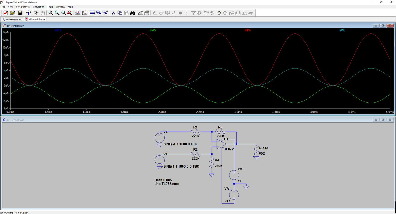
From the simulation through LTspice I see a current swing of 14uA across the resistors, so something very small like 1/8W should work well isn't it?
Here are the results for i through R1, R2, R3 and R4. Rload is set to 652 ohms according to the datasheet of the driver board.
...Anaview AMS 1000 ... add a vu meter kit...
There are many ways to peel a banana.
As you say, the "kit" probably expects an unbalanced input, but you plan balanced input. On the other hand, a 500 WATT amplifier can *easily* drive a meter, even an insensitive low-cost 1mA meter. Even with high-drop Silicon rectifier. AND the raw meter is full-floating, avoids all concern about balanced or unbalanced.
You need a series resistor. I am guessing a 1mA meter and 31.6V amplifier output, so about 33K. Power past clipping may exceed 0.030W; a 1/8W part is ample.
You need a rectifier. For little 1V line-level signals the 0.6V drop of a cheap generic Silicon diode is embarrassing. At 31V, not so much. This is a 20dB (or perhaps 25dB) scale. It won't twitch below 3V. The 1.2V drop of a $1 FWB is a teensy error at the lowest levels you can hope to read. (The cheap meter's own errors will be worse.)
IMHO, this is eye-candy at most. Anyway there is little point in "measuring" speech/music signals-- they jump all over. To know "clipping" you need a Peak Detector, a more complicated circuit. And in context of a 500 Watt amplifier, a 20+dB range does NOT cover many "reasonable" listening levels. (I recall a fine dining establishment with a 200W amp with 40dB meters, they seated us next to that amp, and the meters twitched about a dozen times the whole meal. As some guy says, most listening is "First Watt".)
Attachments
Last edited:
Yup, the problem of the scale is something i've noticed just yesterday since the preamp was setted to - 45.5dB, but i've found a possible solution: i'll use the difference amplifier but with a little tweak: i'll add in parallel to R3 another resistor of lower value that acts as a gain for the instrument: using the "low gain" (Rgain closed on R3) i can align the 0dB of the VU to the clip signal of the amp (i've a resistor of 8 ohm 200W to perform dummy loads tests). For something more fancy, i'll simply add a gain of 10 (+10dB) or maybe 100 (+20dB) that should be more than enough to have a real scale of -30dB/-10dB or -40dB/-20dB.There are many ways to peel a banana.
As you say, the "kit" probably expects an unbalanced input, but you plan balanced input. On the other hand, a 500 WATT amplifier can *easily* drive a meter, even an insensitive low-cost 1mA meter. Even with high-drop Silicon rectifier. AND the raw meter is full-floating, avoids all concern about balanced or unbalanced.
You need a series resistor. I am guessing a 1mA meter and 31.6V amplifier output, so about 33K. Power past clipping may exceed 0.030W; a 1/8W part is ample.
You need a rectifier. For little 1V line-level signals the 0.6V drop of a cheap generic Silicon diode is embarrassing. At 31V, not so much. This is a 20dB (or perhaps 25dB) scale. It won't twitch below 3V. The 1.2V drop of a $1 FWB is a teensy error at the lowest levels you can hope to read. (The cheap meter's own errors will be worse.)
IMHO, this is eye-candy at most. Anyway there is little point in "measuring" speech/music signals-- they jump all over. To know "clipping" you need a Peak Detector, a more complicated circuit. And in context of a 500 Watt amplifier, a 20+dB range does NOT cover many "reasonable" listening levels. (I recall a fine dining establishment with a 200W amp with 40dB meters, they seated us next to that amp, and the meters twitched about a dozen times the whole meal. As some guy says, most listening is "First Watt".)
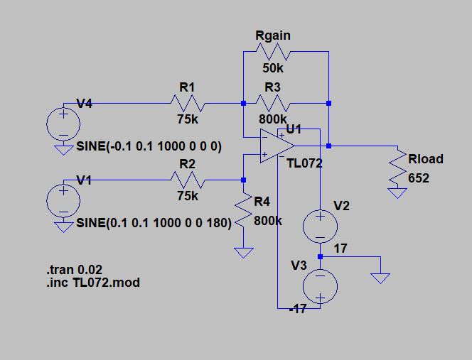
I have to do some calculations but i think that R1=R2=100k and R3=R4=400k with Rgain of 20k should be ok for a gain of 10 between H and L.
Ok i've done some calculations and the result are those two circuits:
this is the one for the gain 1x-10x (+10dB)
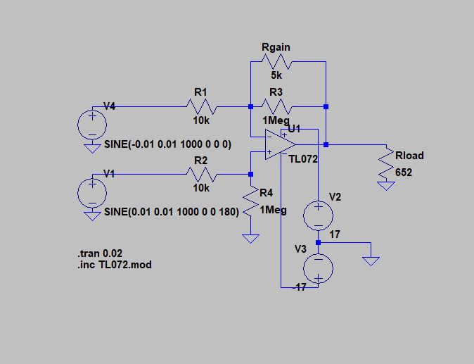
and this is the one for 1x-100x (+20dB)
what do you think? Will it work well? The gain will be toggled with a switch near the VU meters. In this way I should be able to use a VU that stops at -20dB all the way down to -40dB. Seems rather obvious that most of the time it will stay at high gain
this is the one for the gain 1x-10x (+10dB)
and this is the one for 1x-100x (+20dB)
what do you think? Will it work well? The gain will be toggled with a switch near the VU meters. In this way I should be able to use a VU that stops at -20dB all the way down to -40dB. Seems rather obvious that most of the time it will stay at high gain
@tomchr and @PRR
How would you recommend to interface the output of a power amplifier into an 10-bit ADC micro-controller pin, with the least impact on amplifier performance?
With a voltage divider. Make sure you protect the uC input so it doesn't see over-voltage in case there's a spike on the amp output.
Tom
Ok i've done some calculations and the result are those two circuits:
this is the one for the gain 1x-10x (+10dB)
Ignorant question on my part: Is VU in power or voltage? If power, your dB calculations are correct. I'm pretty sure VU is relative to dBV or dBu, though.
I'm concerned by the high impedances in your circuit. I suppose you're not overly concerned about noise and the input bias current of the CMOS opamp should be low, but still... I'd probably go with 220k/2.2k and add a buffer on the input.
Or 220k/22k and not have the gain switch.
Tom
Last edited:
...Is VU in power or voltage?....
It's worth studying this topic. If only to understand that VU is obsolete.
That "kit" is not a VU meter; it is just printed to look like one.
A True VU meter is a sensitive damped voltage meter.
If we know Voltage and Resistance, we know Power.
The True VU meter was calibrated in reference to 0.775V in 600 Ohms. Which is 1 milliWatt, 0 dBm. It is normally used with an attenuator; "0VU" can be +8dBm for broadcast work or +4dBm for recording studio, or whatever a tape deck needs to hit 3% THD.
The True VU is *damped* (when facing rated impedance) to not over-shoot much on transients. It always under-reads speech/music transients but the consistent damping allows experienced judgement of headroom in a known channel. That in fact was its design goal: monitoring levels on radio network land-lines with hundreds of repeaters, with tone for precision or with program for knowing when there was a problem. Tone does not need damping but program sure does. A well-damped meter has a big magnet; a True VU is heavy. And not cheap: a True VU meter was $150 in the 1950s and much more by 1970 when it faded from new gear.
Instead he has two 5-buck meters and a 9-buck PCB. The meters probably have "no" damping. It is possible the PCB is not only a rectifier (and better than Copper-Oxide) but has rise-fall damping.
Note that the range 20-10-7 VU is equal spacing for 10dB and 3dB. That can't be right except for some fortuitous combination of errors. The "+5VU" mark is not in the 1939 spec (which was very comprehensive, even specifying the Pantone color of the background).
Aside from probably not being much like a real VU meter, a real VU meter is a very limited thing. It is very good in the -7VU to +3VU range, can hardly tell -10VU from -20VU, and is silent below that. OTOH a large hi-fi amp on non-pop music is worked all over a 90dB range. And a 500W amp may only come above 50W ("-10VU") on Saturday nights.
Yes, a sensitivity switch can be used. The problem is you set it for 0.5W-5W, have another bottle of wine, turn-up the volume to hundreds of Watts forgetting the switch is in the low-Watt position. It is possible to design the driver so it won't burn the meter. That was essential in our Boonton and H-P audio bench-meters. I'm not sure why a $19 product would bother.
The VU meter comes from a time and application where a "passive" meter was desired, and its limitations accepted. Around the same time in smaller systems the BBC and others developed active meters. A BBC "PPM" covers around 50dB spread out linearly, is peak-detect (not average) with slow fall-back, and also has hi-Z input.
There were several Japanese chips specifically designed to drive low-cost meters with wide-range audio, doing log or root compression, time-constants, and damping, for the fancier Japanese power amps.
VU is not obsolete, it is a measure of apparent loudness and a indication of power level. A VU meter is designed to meter pro level (+4 dbm ) line level signals out of a mixer or in/out of a tape machine where the average level is supposed to stay around 0VU. Looks nice on a power amp but otherwise useless.
I'm not sure, this is the point. McIntosh uses a watt-scale, but from what i remember, all VU are relative to dBu. Plus, i don't know if that kit is really a logarithmic kit, for 14$...Ignorant question on my part: Is VU in power or voltage? If power, your dB calculations are correct. I'm pretty sure VU is relative to dBV or dBu, though.
I'm concerned by the high impedances in your circuit. I suppose you're not overly concerned about noise and the input bias current of the CMOS opamp should be low, but still... I'd probably go with 220k/2.2k and add a buffer on the input.
Or 220k/22k and not have the gain switch.
Tom
I have to do some physical tests though, because i'm worried that a gain of 100x will leave a "no-detection zone", for example 30W may be too much for the low gain but not enough for the high gain, it's not easy to sizing the resistors without even knowing the clipping input voltage of that module
It's worth studying this topic. If only to understand that VU is obsolete.
That "kit" is not a VU meter; it is just printed to look like one.
A True VU meter is a sensitive damped voltage meter.
If we know Voltage and Resistance, we know Power.
The True VU meter was calibrated in reference to 0.775V in 600 Ohms. Which is 1 milliWatt, 0 dBm. It is normally used with an attenuator; "0VU" can be +8dBm for broadcast work or +4dBm for recording studio, or whatever a tape deck needs to hit 3% THD.
The True VU is *damped* (when facing rated impedance) to not over-shoot much on transients. It always under-reads speech/music transients but the consistent damping allows experienced judgement of headroom in a known channel. That in fact was its design goal: monitoring levels on radio network land-lines with hundreds of repeaters, with tone for precision or with program for knowing when there was a problem. Tone does not need damping but program sure does. A well-damped meter has a big magnet; a True VU is heavy. And not cheap: a True VU meter was $150 in the 1950s and much more by 1970 when it faded from new gear.
Instead he has two 5-buck meters and a 9-buck PCB. The meters probably have "no" damping. It is possible the PCB is not only a rectifier (and better than Copper-Oxide) but has rise-fall damping.
Note that the range 20-10-7 VU is equal spacing for 10dB and 3dB. That can't be right except for some fortuitous combination of errors. The "+5VU" mark is not in the 1939 spec (which was very comprehensive, even specifying the Pantone color of the background).
Aside from probably not being much like a real VU meter, a real VU meter is a very limited thing. It is very good in the -7VU to +3VU range, can hardly tell -10VU from -20VU, and is silent below that. OTOH a large hi-fi amp on non-pop music is worked all over a 90dB range. And a 500W amp may only come above 50W ("-10VU") on Saturday nights.
Yes, a sensitivity switch can be used. The problem is you set it for 0.5W-5W, have another bottle of wine, turn-up the volume to hundreds of Watts forgetting the switch is in the low-Watt position. It is possible to design the driver so it won't burn the meter. That was essential in our Boonton and H-P audio bench-meters. I'm not sure why a $19 product would bother.
The VU meter comes from a time and application where a "passive" meter was desired, and its limitations accepted. Around the same time in smaller systems the BBC and others developed active meters. A BBC "PPM" covers around 50dB spread out linearly, is peak-detect (not average) with slow fall-back, and also has hi-Z input.
There were several Japanese chips specifically designed to drive low-cost meters with wide-range audio, doing log or root compression, time-constants, and damping, for the fancier Japanese power amps.
interesting post, thanks.
I'm not seeking a precision vu meter however, only something fancy in order to give the amp a retro look, plus to have something to look at when i'm listening to music. For 14$ i never expected it to be a real vu meter, just something fun to add as a decoration.
just something fun to add as a decoration.
Watching an oscilloscope trace dancing around can be amusing
Watching an oscilloscope trace dancing around can be amusing
yup, but the VU is included in the amp and has that retro look that is really nice
- Status
- This old topic is closed. If you want to reopen this topic, contact a moderator using the "Report Post" button.
- Home
- Amplifiers
- Chip Amps
- vu meter on balanced amp