Hi
I just completed a LM1875 Room amp, I tested it with no load with a meter for DC output which is 100mV. But when I connect it to a speaker it goes 0.
The speaker is rated as 25 watts 8 ohms. I tried all my speakers even dummy loads, it does same thing.
I loaded it to the oscilloscope it has a signal when I tap the inputs but when connected to a load it goes flat lined.
I used +/- 22v (2A) power supply, I even used a +/-15v (3A)but still fail to make it sing.
I was frustrated for the effort and time I spent just make this project. Got any ideas whats wrong with it?
What happens if you load it with say a 1k or a 100 ohm in place of the speaker ? Does the output collapse then. We do also need to know that the output is correct with no load. You have a scope and so you can measure this accurately. Use a sine wave and see the output is of the expected amplitude (as set by the feedback attenuation network) and distortion free.
Are the rails remaining correct when it 'flat lines' ?
And knowing from past forum experience (sorry... have to ask) are you connecting the speaker between chip output and ground (the 0V line) and NOT between output and negative rail ?
Are the rails remaining correct when it 'flat lines' ?
And knowing from past forum experience (sorry... have to ask
) are you connecting the speaker between chip output and ground (the 0V line) and NOT between output and negative rail ?I connect the load to output and connected the other wire to ground. The supply voltage is 44.8v between anode and cathode with load connected. 44.2v when disconnected. Maybe the PSU is the problem since it has 5,600 uF/50v filter caps in split configuration, Does it matter? I would like to add, the scope readings are a bit erratic with load connected. Maybe the output collapsed when a load was connected. I will try to tin the paths, I was using a 1oz board. Not to mention it went through a little sanding.
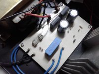
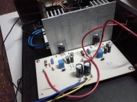
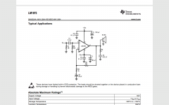
These are the layout and actual images of the projects, its a bit crude I made it from parts laying around my workplace. And the schematics, I just added a 10 ohm paralleled with a 4.7uH on the output ( someone just told me but not my idea ).
Attachments
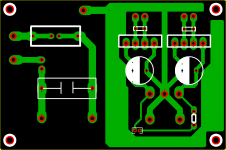
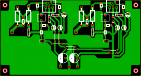

Maybe I'm going crosseyed but I'm struggling to make sense of the board layout tbh. Is that a top view or bottom view ?
Bottom left pin on the layout looks to be pin 1 (configured as input on the layout) and yet it is next to pin 4 (the output). Also that bottom left pin is floating at DC if the large rectangle is meant to be C1.
Bottom left pin on the layout looks to be pin 1 (configured as input on the layout) and yet it is next to pin 4 (the output). Also that bottom left pin is floating at DC if the large rectangle is meant to be C1.
What are the DCR and current ratings of those inductors ? People usually use small homemade air coils there.And the schematics, I just added a 10 ohm paralleled with a 4.7uH on the output ( someone just told me but not my idea ).
Yes, the rectangular thingy is the 2.2 uF input capacitor.
So that is pin 1. We are looking down on the board from above. R2 is missing, the pin is floating.
The pin to the above right of this is pin 2 on the real chip and yet you seem to have the PCB configured as if it were pin 4.
It looks like you have the board layout incorrect to me.
- Status
- This old topic is closed. If you want to reopen this topic, contact a moderator using the "Report Post" button.
- Home
- Amplifiers
- Chip Amps
- LM1875 working but cuts off when a speaker is connected.