Hi there!
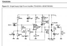
I decided to try scematic TDA2030 as a tranzistor driver. And i have some questions about that schematic.
Did anyone do such a scheme? Does it sound normal? Will that schematic give me some troubles with installation and tuning?
Starting at what output power will additional transistors begin working?
What power supply unit should I use? How many watts?
And in this scheme, the gain factor is 10 as I understand it. Is this enough for an input signal level of 500 mV? What values of pR4 and R5 should I use?
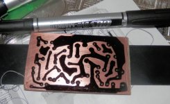
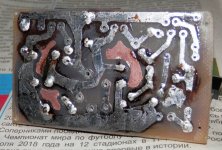
I will definitely try this scheme. I already made a circuit board and almost soldered all the components.
I decided to try scematic TDA2030 as a tranzistor driver. And i have some questions about that schematic.
Did anyone do such a scheme? Does it sound normal? Will that schematic give me some troubles with installation and tuning?
Starting at what output power will additional transistors begin working?
What power supply unit should I use? How many watts?
And in this scheme, the gain factor is 10 as I understand it. Is this enough for an input signal level of 500 mV? What values of pR4 and R5 should I use?
I will definitely try this scheme. I already made a circuit board and almost soldered all the components.
Attachments
hello.
that schematic is similar to the one in the sgs(-thomson) ........page 6
TDA2030A Datasheet pdf - 14W Hi-Fi audio amplifier. Supply voltage Vs: +-6V,min; +-22V,max . Quiescent drain current Id: 50Ma,typ; 80mA,max. - Contek Microelectronics
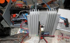
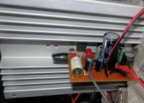
you need proper heatsinks;
do not forget the isolating material for the transistors and the ic;
if the voltage drop across the 1,5ohm res is bigger than 0,6volt the transistors begin to conduct ( ......0,4A current......could be 0,3W Pout with a 4ohm speaker);
that schematic is similar to the one in the sgs(-thomson) ........page 6
TDA2030A Datasheet pdf - 14W Hi-Fi audio amplifier. Supply voltage Vs: +-6V,min; +-22V,max . Quiescent drain current Id: 50Ma,typ; 80mA,max. - Contek Microelectronics
you need proper heatsinks;
do not forget the isolating material for the transistors and the ic;
if the voltage drop across the 1,5ohm res is bigger than 0,6volt the transistors begin to conduct ( ......0,4A current......could be 0,3W Pout with a 4ohm speaker);
Proceed with extra caution.
Why? What could be the problem?
Your circuit is a worked example from the data sheet and so should be OK, and particularly as you are using the correct PCB.
It will be interesting to know how you find it.
Lots of these (a variation on the same topology) were made in 80s, this was a popular design at that time, published in a local tech magazine, probably direct copy from the factory brochure, "no setup required, plug-and-play" etc. I made some, people I knew made some and there was a common theme: the tendency to blow up randomly without any forewarning. No amount of oversized heatsinking could cure that.
So proceed with extra caution and double ckeck everything.
Who knows, it may work for you without a hiccup.
I wonder the purpose of this circuit.
The power output of the TDA2030 remains the same.
Maybe it's meant to drive 2 ohms.
But like anti said:

The power output of the TDA2030 remains the same.
Maybe it's meant to drive 2 ohms.
But like anti said:
Proceed with extra caution.
Chips like the TDA20xx are not intended to be used at max Vcc and lowest impedance simultaneously. Adding the extra transistors lets you do both. Run it at 12-18 volts where the chip is fat and happy, you will see no improvement. Run it at 30 volts where the chip has trouble with 2 ohms, you would be able to run harder before it goes into current or thermal limit. The downside is you lose all that internal protection built into the chip. Overload the transistors and poof you buy another pair.
And the chip. IME, for some reason the chip tended to die with the transistors....
Overload the transistors and poof you buy another pair.
...
An externally hosted image should be here but it was not working when we last tested it.
The PCB is too huge. It's like an airport And on the contrary, output and power supply's caps are too small. They are, especially output cap, much bigger in real.
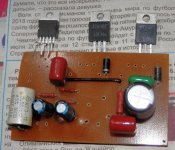
So I've already finished one channel of my amp and listened it to check how it sounds. It started to work immediately without any problems. I temporarily, for checking, took the power for it from my other amplifier. It's 37 V and 2*4700 uF.
Well, I don't know what to say about it. It seems there is a difference and it seems there is no difference between TDA + transistors and bare chip.
Who made or listened that scematic? What was your feeling?
And on the contrary, output and power supply's caps are too small. They are, especially output cap, much bigger in real.So I've already finished one channel of my amp and listened it to check how it sounds. It started to work immediately without any problems. I temporarily, for checking, took the power for it from my other amplifier. It's 37 V and 2*4700 uF.
Well, I don't know what to say about it. It seems there is a difference and it seems there is no difference between TDA + transistors and bare chip.
Who made or listened that scematic? What was your feeling?
Attachments
Thank yougood to hear you have it working OK.
And I want to do some tests of that amp with an oscilloscope. For example, the shape of a sinusoid and synchronism of opening of transistors.
Thank you
And I want to do some tests of that amp with an oscilloscope. For example, the shape of a sinusoid and synchronism of opening of transistors.
......you can build a fuse into the line from the psu to the tda2030 amp board -
as a little protection against unwanted events.
A little protection is exactly right - against the fire that would otherwise happen when the transistor shorts out.
There is no real way to protect the transistors without adding yet still more parts and compromising output voltage swing. Except maybe using a switching power supply with a really fast current limiter.
There is no real way to protect the transistors without adding yet still more parts and compromising output voltage swing. Except maybe using a switching power supply with a really fast current limiter.
I will.......you can build a fuse into the line from the psu
There is no need to protect transistors. They are the cheapiest elements of the scheme. I shall build a fuse into the psu's line for general protection and that will be enought.There is no real way to protect the transistors
The most important thing is to protect the speakers. But I'm using single power supply unit and it means my speakers are protected by default
You should find the TDA2030 does an admirable job of protecting the fuse. That was always my experience of them.
AC coupling has a few advantages, and speaker safety is one of them.
If I were testing something like this then I would try loading it down to say 1.5 ohm and gently see how thing look at say 4 or 5 volts peak amplitude across the load.
AC coupling has a few advantages, and speaker safety is one of them.
If I were testing something like this then I would try loading it down to say 1.5 ohm and gently see how thing look at say 4 or 5 volts peak amplitude across the load.
- Home
- Amplifiers
- Chip Amps
- TDA2030 with transistors