mjf,
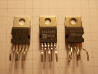
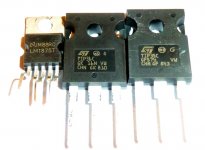
Do you use an genuine TDA2040? If I may, I would also like to see photos of its front and back.
Attachments
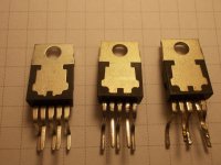
mjf, thank you for photos.
What amount of gain did you set?
And how do you think, is it possible to replase common transistors with darlington transistors?
Why do you want to buy TDA 2030? In fact TDA 2040 is practically complete analog.
I have got only these fake chips. LM1875, TDA2030/50, all of them are are absolutely identical with the exeption of label. But even fake TDA2030 works quite well.
Attachments
standard setting , gain is 23 x (22k/1k in the feedback);
perhaps it is possible to try out darlington transistors, but it makes no sense to me. the chipamp has per se enough power to drive non critical speaker loads. and with low impedance boxes a normal power bjt should work.........;
tda2030 - i want to try it out (and the tda2040 is not available anymore).
Hi people,
I'd like to try a chipamp with output transistors circuit, but I'm a total newbie and need help.
I've built several chipamps with the LM1875 and the TDA7293 until now, but I always just copied schematics from the net and made eventually some little variations where I knew it was safe.
I have surfed the net for examples and sure found some circuits which are pretty similar to the one I'd like to built.
At the moment I have got a Mivoc AW 3000 in a 45l sealed box, driven by two paralleld TDA7293 as subwoofer and I've got a kit for three TDA's lying around. I've done the optimizations for better bass reproduction which can be found here on the board and everywhere else in the net and I am totally satisfied with the result ... but, I would like to try a LM1875 with transistors anyway.
I've got a few LM1875 (which was my 1st love as a chipamp) to play around with, and I've got the complete output stage of a Rotel RA-06 + the original transformer. So I'd like to use these in combination with a LM1875 and I hope, I can use the original toroid with +/-48V DC for the transistors, which are four 2SB817, four 2SD1047 and a pair of 2SA1837/ 2SC4793 as drivers (don't know if they're needed).
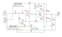
I found the attached circuits on the net, what must I change, to make, for example, the one with the LM1875 fitting with my parts?
best regards
Jochen
I'd like to try a chipamp with output transistors circuit, but I'm a total newbie and need help.
I've built several chipamps with the LM1875 and the TDA7293 until now, but I always just copied schematics from the net and made eventually some little variations where I knew it was safe.
I have surfed the net for examples and sure found some circuits which are pretty similar to the one I'd like to built.
At the moment I have got a Mivoc AW 3000 in a 45l sealed box, driven by two paralleld TDA7293 as subwoofer and I've got a kit for three TDA's lying around. I've done the optimizations for better bass reproduction which can be found here on the board and everywhere else in the net and I am totally satisfied with the result ... but, I would like to try a LM1875 with transistors anyway.
I've got a few LM1875 (which was my 1st love as a chipamp) to play around with, and I've got the complete output stage of a Rotel RA-06 + the original transformer. So I'd like to use these in combination with a LM1875 and I hope, I can use the original toroid with +/-48V DC for the transistors, which are four 2SB817, four 2SD1047 and a pair of 2SA1837/ 2SC4793 as drivers (don't know if they're needed).
I found the attached circuits on the net, what must I change, to make, for example, the one with the LM1875 fitting with my parts?
best regards
Jochen
Attachments
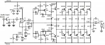
The first circuit doesnt need a power op amp on the front - it is quite happy with a regular 5532, LF353, or even 318 (as in the original that it was copied from). On 48 volt rails your transistor complement would be fine. The second circuit has the wrong polarity fitted - needs PNP's in the top, with collector to output. And it does not benefit from darlington connection. You would be better off paralleling, but that is at diminishing return on any voltage that an 1875 would survive.
Hey, thanks for your answers! But, don't think so much about the schematics on the pictures, they only should be examples for the direction I'd like to go. Could you give me some hints what I can do with the parts I've got. How can I use different voltages for the LM1875 and the transistors? I've got toroids for both (+/-28V and +/-48V). As transistors, I've got the four 2SB817/ 2SD1047 or if that would be a better option two pairs of 2SA1943 and 2SC5200. If drivers would be needed, I got 2SA1837/ 2SC4793 or TIP41C/ TIP42C.
I'm not in a hurry, because I'm also working on satellite speakers which will be a lot of work. But when evening comes and I must stop making so much noise, I'd like to solder and try things out a little. I'm thankful for every help.
best regards
Jochen[COLOR=inherit !important]
#s3gt_translate_tooltip_mini { display: none !important; }[/COLOR]
The LM1875 has a maximum voltage rating of 60 volts and so that means no higher than -/+30 volts DC which in turn means a transformer of no more than around 21-0-21 volts AC.
In practice an 18-0-18 would be a good choice.
I would have thought a tried and tested circuit such as the one the guys in this thread have constructed would be a good starting point tbh. Using the low value resistors in series with the chip supply means that no drivers are needed, the chip pulls more current than the 'helper' transistors would ever need to drive them.
I'm using 18- 0- 18/ 120W in my satellite speakers where they have got to feed three hungry LM1875's. I've heard the speakers and they are great, but the wood i found on the street was crap, so I'm building new cases now. I will also be reading some articles about the basics of amplifiers (at the moment this > Amplifiers: Solid state amplifiers) and did some first steps in TINA-TI.
What I dislike at the tested circuits is that the transistors are running at the same voltages as the chipamp. I don't think a pair of 2SA1943/ 2SC5200 @ +/-25V has the punch that is needed for a 12" woofer.
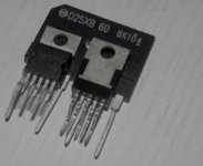
As I said, it's just playing around and maybe learning a bit, it's not urgent. I'll keep on looking around, peeking here & there, and maybe I'll get my circuit together") . The pic is the three LM1875 just before the first test, but at this time still in the crappy cases. I've got to finish the new ones, I want that wonderful music back!
. The pic is the three LM1875 just before the first test, but at this time still in the crappy cases. I've got to finish the new ones, I want that wonderful music back!
What I dislike at the tested circuits is that the transistors are running at the same voltages as the chipamp. I don't think a pair of 2SA1943/ 2SC5200 @ +/-25V has the punch that is needed for a 12" woofer.
As I said, it's just playing around and maybe learning a bit, it's not urgent. I'll keep on looking around, peeking here & there, and maybe I'll get my circuit together
. The pic is the three LM1875 just before the first test, but at this time still in the crappy cases. I've got to finish the new ones, I want that wonderful music back!Attachments
This thread should give you a good idea of the actual voltage levels you need to swing across your speakers (and sub).
A Test. How much Voltage (power) do your speakers need?
The LM3886 is one chip that will operate at higher supply voltages, but it is slightly more complex to use.
A Test. How much Voltage (power) do your speakers need?
The LM3886 is one chip that will operate at higher supply voltages, but it is slightly more complex to use.
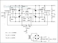
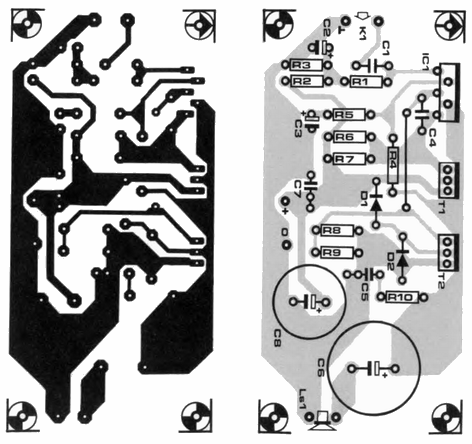
I know this thread is quite old now but this information is still valid. The link below was first published in the Elector Electronics Dec 1992 edition.
I built a pair of these amps from this link together with the PCB layout. Using a 20 - 0 - 20 120VA transformer and the BD911 & BD912 output transistors.
Been running these amps on a 4ohm loads for almost a year now with no issues or stability problems. The sound quality is exceptionally good for such a cheap basic amplifier and is comparable to some transistor amps.
I do want to try and use the "better quality" LM1875 and see if there is any audible difference in sound quality.
I am very happy with them and the only reason to change amps would be to build a higher power 100W amp in the future.
TDA2030 Audio Amplifier 1 x40W ~ AmplifierCircuits.com
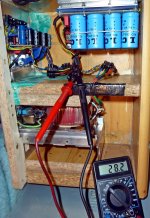
PSU & Voltage details
Measuring with a multimeter on the AC side of the bridge rectifier I am measuring 21.6Vac and on the 4700uf smoothing cap I am measuring 28.9Vdc.
Using the formula Vdc = Vac x 1.414 to calculate DC RMS voltage of the bridge rectifier you would expect 30.5Vdc but you also need to subtract the voltage drop of the bridge rectifier diodes 0.7v x 2 = 1.4V. You would then expect to get 29.1Vdc which is almost what I am measuring with the multimeter.
The absolute maximum for the TDA2030 is 36V and all the parameters on the datasheet are measured at +-14v or 28v so I think it is the safe operating margins for the chip.
As I mentioned my amps have been running for almost a year now without any problems with these PSU voltages.
Wouldn't a 20-0-20 toroid generate rails of more than the absolute max rating of the TDA2030 (44 volts total)?
Sorry but I was also not quite correct and should have been clearer, my transformer is 20 + 20 120VA multitap and not centre tap transformer. I am using 1x 20V tap for each L + R channel individually with 2x bridge rectifiers, they are essentially 2 completely separate power supplies from 1 transformer.
Ah, OK It did read as though you you had it configured for dual rail operation. 36 volts total is the recommended continuous maximum for normal operation but the chip has an absolute maximum rating of 44 volts (from the STmicroelectronincs data sheet).
Your configuration is fine
It did read as though you you had it configured for dual rail operation. 36 volts total is the recommended continuous maximum for normal operation but the chip has an absolute maximum rating of 44 volts (from the STmicroelectronincs data sheet). Your configuration is fine
One might add a NPN power device to the positive side, that is driven by T1's collector, and a PNP one to the negative, and provide dual rails. This way the last power devices could be fed from higher voltage rails. Hence more power is possible from a single amp.
It's just a mental experiment, though. Don't ask me about stability.
Best regards!
It's just a mental experiment, though. Don't ask me about stability
.Best regards!
One might add a NPN power device to the positive side, that is driven by T1's collector, and a PNP one to the negative, and provide dual rails. This way the last power devices could be fed from higher voltage rails. Hence more power is possible from a single amp.
It's just a mental experiment, though. Don't ask me about stability
Best regards!
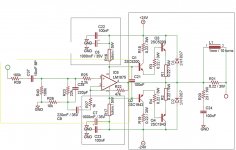
Yes Agreed, in fact, Rod Elliot at Elliott Sound Products has written a really nice technical article on designs using Power Op-Amps + Booster Transistors. He explains using the split rail power supply as you suggested. See link below.
IC Power Amps
He also mentions in the article that the amplifiers distortion increases but I have to admit that I do not hear or notice this. I also do not have any test gear so are unable to confirm.
I have already done a quick split rail design using the LM1875 chip that can use a higher supply voltage and has better distortion figures than the TDA2030. Calculations indicate it could drive up to 90W into 4ohms. Have not had any time to build and test it though.
Attachments
- Home
- Amplifiers
- Chip Amps
- TDA2030 with transistors