I recently built this amp "K.GUSS K-L68 LM3886 JRC5534DD OP07" and I'm having problems getting it working right. There is jumper on it for "OS or CS" after the op amp stage. From what I gather, OS sets the op amp to follower. And, CS sets the 4.7uf caps to both ends shorted. Any ideas which I should do? When I run the amp without either shorted, I get no bass and one of my speakers seems inverted. Amps don't even warm up slightly.
Attachments
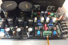
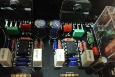
I did email the vendor, but they didn't have an answer for me. So far, I know that I have 36v going to both pins, 1 and 5. I have +15v and -15v going to the op amps. When I connect my phone to the amp, there isn't much noise. However, when I connect my computer (minidsp 2x4 hd) there is significant noise. That would seem like a ground loop problem, but that still doesn't solve the no bass problem. Somewhere along the line the filters or off, I think. I noticed that some of these boards have 220pf caps at the input, rather than the 680pf mine has. Other than that, the 6.8nf cap near the chip is 4.7nf on some of the other chips.
Attachments
I noticed that a diode at the power supply side of the board is facing a different direction on the one that I have. The diode trace leads back to the other side of the board where the C1237HA speaker protector is. The voltage across the cathode (striped side) is ~4.5v, while the anode reads -8v. Could this be backwards?
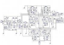
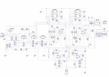
I have had (my first) a go at reverse engineer this board.
I have two circuits, one with the part numbers (R1, R2...) and the other with the component values.
Here is the one with the values which should work in conjunction with the images in the previous posts.
Let me know if something doesn’t look correct.
Is it possible to make the uploaded image larger?
Attachments
Last edited:
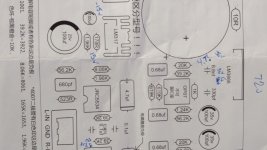
 Can you please post a full size pic of your parts list?
As far as I can see the values are the same as the ones on the board in this thread.
This destail in this upload are a bit easier to see.
That is (IMO) one of the most unreadable schematics I've ever seen. Looks too much like a plate of spaghetti.
I'm sure it could create a valid netlist but..
G²
ICG, Is there a reason that I would want to couple the input? If so, would AC or DC be better.
Also, I keep coming back to that diode. It looks like, from the schematic, that it's connected to PIN 5 of C1237HA. PIN 5 should be ground, which means that the diode should probably be reversed. Right?
Also, I keep coming back to that diode. It looks like, from the schematic, that it's connected to PIN 5 of C1237HA. PIN 5 should be ground, which means that the diode should probably be reversed. Right?
ICG, Is there a reason that I would want to couple the input? If so, would AC or DC be better.
Well, technically none is 'better', just different. DC coupling does not have the phase shift of the input capacitor and (theoretically possible) a frequency response down to 0 Hz. While the latter is practically useless, the former isn't always that trivial, it's a further part in the signal path and does impact the sound quality more or less. The downside is once you got a signal source with a DC-offset, it also amplifies the offset, that's why most of the times an AC coupling is preferred.
Also, I keep coming back to that diode. It looks like, from the schematic, that it's connected to PIN 5 of C1237HA. PIN 5 should be ground, which means that the diode should probably be reversed. Right?
No, that's correct, that's to detect if the transformer is still working. If the voltage through the diode and the capacitor drops, the protection IC knows the power was switched off and releases the relay to prevent the switch off noise or distortion while the power supply caps are still having 'juice' but drop in voltage.
Edit: Pin 5 is wrong, that has to go to pin 4.
Last edited:
I tried flipping the diode around, but it didn't work. The relay never clicked and the speakers stayed disconnected. I'll flip it back around. This has got to be something with the feedback loop, maybe a grounding issue. Other than the electrolytics, is it possible that the polarity matters on one of the film/ceramic caps? Also, there are 4 619k resistors on my board that are 681k on the schematic, and 2 39.2k on mine instead of 31.6k.
- Status
- This old topic is closed. If you want to reopen this topic, contact a moderator using the "Report Post" button.
- Home
- Amplifiers
- Chip Amps
- LM3886 help, please!