I would not worry about that.One thing I noticed about the minidsp is that it isn't grounded to the case it comes in. The PCB is basically floating inside the case, and the ports are insulated from grounding it to the case. Could this be causing the problem?
I went ahead and scraped away some paint and used a non painted screw to get it grounded to the case. It did absolutely nothing.
So it looks like the CS must be AC coupled since it's routing the signal through the 4.7uf cap. So maybe I would be better off going the other route to avoid having the cap in the audio path. Both ways eliminate the oscillations, but AC coupled seems slightly quieter. Any thoughts?
I should also note that the amps aren't in a case yet (on an aluminum grounded plane, right now), and I haven't put in an AC filter yet (which I will). So that may help reduce the noise.
I tend to think that one should not make assumptions that the source is DC free, but I think that is what you meant to say.
Exactly...or to be more precise measure it!
")
I went ahead and scraped away some paint and used a non painted screw to get it grounded to the case. It did absolutely nothing.
I should also note that the amps aren't in a case yet (on an aluminum grounded plane, right now), and I haven't put in an AC filter yet (which I will). So that may help reduce the noise.
Since you have an oscilloscope, it would be wise to see what the oscilloscope shows on amp output...I could bet that it would show the 60Hz harmonics from PSU (120Hz, 180Hz, 240Hz....). The reason for this is bad handling of signal and power ground routes on amp pcb (no/bed separation on signal and power ground routes).
The situation is more problematic because:
- there is only one PSU to power two amplifiers
- power connection provided is for transformer with center tap secondary only and one greatz
All listed leads the loops in ground plane (60Hz harmonics at amp output) if one is not careful about psb design.
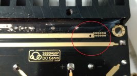
I did see 60Hz harmonics with the oscilloscope, yesterday. I also noticed something that I had missed. When I looking over the grounding traces I noticed an unmarked hole on the top plane. That plane appears to be the signal ground since it runs near the chip and relay. I'm going to connect a wire to the hole and route it my central grounding point. It looks like they actually did a pretty good job of keeping the high and low voltage grounds separated.
Attachments
It's not about high/low voltage grounds (all grounds should be 0V anywayIt looks like they actually did a pretty good job of keeping the high and low voltage grounds separated.
), it's about current in grounds (routes and planes) and how the circulate.Yeah, yeah, I know. You know what the say about people who "assume". So, I've got the noise down to a pretty low level, and the oscillation is not as bad. But, I'm still not there yet. I had read somewhere about connecting a cap at the input from the source. Any idea how this is done?
I must admit, the sound is much better than the tda7498's that I've been using. I keep having to reduce the gain on the tweeters because the treble is sharp enough to cut steel (in a good way). Also, the bass seems a lot more impactful. As much as it can be, anyway, on these 3.5 inch Dayton Audio ND91's.
No fuses?No damage, I stopped it in time. I believe it was the insulation around the wire that I connected to the negative voltage rail I thought was a ground.

- Status
- This old topic is closed. If you want to reopen this topic, contact a moderator using the "Report Post" button.
- Home
- Amplifiers
- Chip Amps
- LM3886 help, please!