You can upgrade the 0,1uF ceramics with poly types (like Wima, Kemet, Epcos; use standard 63V types). You can upgrade the small ceramics (I suppose these are 1nF and 4,7nF) with multilayer ceramics, preferrably NPO or COG type (X7R is also workable).
I would replace the resistors with standard 0,25W or 0,6W metal-film resistors; nothing special - f.e. Yageo MF0207 type should be quite adequate.
For the lytics, I would use "FT Cap" brand axials as I said before - 25V or 40V grade, standard A 85deg C series. They work fine, look vintage and classy. To make the most of their looks you would have to clean the board with alcohole (isopropyl) and an old toothbrush. After that, use a hairdryer. (This procedure makes it a proper refurb).
If you havent already acquired the TCA940s, you may get a slight power boost with TBA810P (the "P" suffix) which is a slightly souped up TBA810S.
Be careful when removing the TBAs, their "wings" will make this a nightmare. A wooden toothpick is a game-changer here. A solder sucker will be less effective than a toothpick.
I didn't particularly like Rudy can't fail; my fave from that album was 'Calling. Then maybe 'New Cadillac, Jimmy Jazz and 'Supermarket. On special occasions also Spanish Bombs and Guns of Brixton.
Dear Anti a part of helping me so much with your precious tips...you're inciting me!!!
here is!!!:
You can crush us
You can bruise us
But you'll have to answer to
Oh oh guns of Brixton!!!
Clash are one of my dearest band of all my life! (please notice I'm "just" 34 years old!!! )
)
Well that said, please dear Anti, forgive me but I prefer the TCA940: at least I know that I can get from this IC 7 or 8 "real" watt (instead of just 4 or 5 watt from the TBA810) and with my old Faital full-range bicone drivers (18 cm, 15 watt max, 4 ohm, 94 dB/1W) surely sound well with the 10 watt max of the TCA940.
You have to know that all the advice you gived me are on my "to-do" list for the upgrade of this project.
I'll call this amp "ANTI MK II"
Thank you again!
P.S.: Just a personal curiosity, Anti: What do you think about the Unitra/Cemi/Tesla old ICs?...I know that they were made in Eastern Europe.What about their quality?
Best regards from Italy
here is!!!:
You can crush us
You can bruise us
But you'll have to answer to
Oh oh guns of Brixton!!!
Clash are one of my dearest band of all my life! (please notice I'm "just" 34 years old!!!
)Well that said, please dear Anti, forgive me but I prefer the TCA940: at least I know that I can get from this IC 7 or 8 "real" watt (instead of just 4 or 5 watt from the TBA810) and with my old Faital full-range bicone drivers (18 cm, 15 watt max, 4 ohm, 94 dB/1W) surely sound well with the 10 watt max of the TCA940.
You have to know that all the advice you gived me are on my "to-do" list for the upgrade of this project.
I'll call this amp "ANTI MK II"
Thank you again!
P.S.: Just a personal curiosity, Anti: What do you think about the Unitra/Cemi/Tesla old ICs?...I know that they were made in Eastern Europe.What about their quality?
Best regards from Italy
You will most likely not be able to get the "full Watts" you want from either chip - because the heatsinks on your board are too small, too weak to allow for the chips to run at full tilt.
I had several boards running with TCA940 in 80's and these were bolted (!) to aluminum extrusion with much larger cooling area. You can try, though - you will most likely have to run them below their max. power rating; which isn't a bad thing per se when you look at it from a certain angle. Translation: stay below or at 20V supply, no more.
The easiest way to squeeze a bit more perceived power within your limitations would be to UP the electrolytic cap values as I mentioned before: replace all 100uF with 220uF and the 1000uF with 2200uF. Use 4700uF or 6800uF psu reservoir cap. You will probably also have to upgrade the rectifier bridge as well to a 2Amp type sooner or later; whichever you find to fit.
The FT Cap 25V or 40V type axials will most likely fit in place of your old caps, as they are physically smaller in size for the given uF capacitance, making it easier to uprate them.
I had a limited experience with Tesla chips used in small radio-cassete players, but not much.
Hi my friend Anti!!! Don't worry about the heat sink: of course I had already thought about this problem.
In fact I'll replace the two TBA810 with their small heat sink with this ones:
IC BAUSTEIN TCA940 mit Kuhlkorper! 12186 | eBay
and furthermore I'll mount (by screwing) them to a very thik alluminium piece (a sort of further external heat sink) that sticks out of the wooden cabinet of the turntable/amp.
By the way, Anti, do you think a 2 ampere rectfier is sufficient to feed two TCA940 at 22 V in a satisfactory way?
Do you know if there're round rectifier bridges with 3 or 4 ampere?
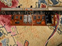
As you can see in the picture, the original round rectifier mounted on the amp board is the "W005".
Thank you for your continuos and costant support
Regards
In fact I'll replace the two TBA810 with their small heat sink with this ones:
IC BAUSTEIN TCA940 mit Kuhlkorper! 12186 | eBay
and furthermore I'll mount (by screwing) them to a very thik alluminium piece (a sort of further external heat sink) that sticks out of the wooden cabinet of the turntable/amp.
By the way, Anti, do you think a 2 ampere rectfier is sufficient to feed two TCA940 at 22 V in a satisfactory way?
Do you know if there're round rectifier bridges with 3 or 4 ampere?
As you can see in the picture, the original round rectifier mounted on the amp board is the "W005".
Thank you for your continuos and costant support
Regards
2Amps won't do it at full tilt. For easy listening no problem.
Try to find KBPC601 or KBPC602 (6A "box" type) and see if you can squeeze it in place of the button type W005 (which a 1'5A type). In a pinch, KBPC101 or KBPC102 (3A types could work).
KBPC's have 10mm or so lead spacing but same pinout as round button types and if you have enough space you can squeeze these in place. You will have to get creative, but it's doable.
EDIT: With 22V you should also make the bootstrap resistor (usually 100 Ohm) and the Zobel resistor (usually 1 Ohm or a couple-Ohm value) replaced by 1W types.
Last edited:
Thank you Anti for the tip about the rectifier!
I know you'll hate mebut please could you explain briefly what is a bootstrap resistor and the Zobel resistor?...please be patient, Anti
At least, could you tell me if these stuff are already present on my amp board and they must be just replaced (or upgrated)?
God bless you!
Regards
I know you'll hate me
but please could you explain briefly what is a bootstrap resistor and the Zobel resistor?...please be patient, AntiAt least, could you tell me if these stuff are already present on my amp board and they must be just replaced (or upgrated)?
God bless you!
Regards
TCA 940
Here's a workable TCA940 schematic. The 100 Ohm resistor (from pin1 to pin4) is a bootstrap resistor. Should be 1W.
The 1 Ohm resistor that goes to ground (in series with a 0,1uF cap from pin2) is the Zobel resistor. It should be 1W as well. (IIRC a better value for this one would be in range 2.2-3.3 Ohm).
You can replace other resistors with standard metal-film resistors like I said before.
Hi Anti!
Please could you help me with your great knowledge?
Please take a look at picture of the amp circuit board (below)...well, could you see the two diodes behind the two grey Elna capacitors (the biggest ones on the PCB)?
On the body of these two diodes I can 1N4001 (and in the bottom part of the diode body there's another number: 710 if this can be an important information).
Could they have some connection to the vu-meters, in your opinion?
Thank you again Anti
regards
Attachments
Could they have some connection to the vu-meters
Yes. Driving VU and other AC Meters - Simple High Performance Circuits

Don't dispair. Here's what I would do.
1) check and decide if you want/need any of "extra features" apart from your board being an amplifier. (like a VUmeter, whatever).
2) if you want "extras", check the connections that the board provides and try to trace your board to get the diagram of how exactly it is done on your board(s). In this case, I would suggest to visit a local service shop / serviceman to help you with the refurb if all of this is starting to get over your head.
3) if you don't want any "extras" and just want a "pure amp", determine which part-positions on your board belong to the core amplifier circuit AND the PSU. In this case, remove any un-necessary and un-related components to the core circuitry. Imho you can do this on your own; you can follow the schematic I linked and use it as a guide to determine "what-is-what-on-the-board".
To renew and refurb the core circuitry, you can follow the recommendations I have outlined in previous posts - these will help you get a little more "oomph" from the TCA (specifically those on electrolytics, resistors and the rectifier bridge).
One final note: I recommended to install 2200uF "output" caps. My "childhood" experience was that for some reason, this was the MAX value that the TCA "liked"; going above 2200uF (eg 3300, 4700uF) could for some reason kill the chip at the power-up.
Hi dear Anti!
As always, thank you for your moral and technical support!
I believe that the best solution is to post a picture where I track the rail of the diodes on the circuit board.
Maybe it's the only way to understand their real function inside the amp circuit board.
Ciao!
As always, thank you for your moral and technical support!
I believe that the best solution is to post a picture where I track the rail of the diodes on the circuit board.
Maybe it's the only way to understand their real function inside the amp circuit board.
Ciao!
Hi Anti!
Just a personal curiosity: instead of using a single amp circuit board (I mean one amp board with two TBA810 or TCA910 like the one I own) could I use two single amp board like these ones:
Zesilovač 10W nf RETRO, STAVEBNICE : H A D E X , spol. s r.o.
or two of these ones, for example:
http://pepina.org/snimki/5146220.jpg
I mean: could I use two separate amp boards like those with my tone and volume controls, with one transformer and one rectifier for the poer supply?
I repeat: it's just to learn new electronic stuff
Thank you very much.
Regrds from Italy
Hi my friend Jimmy "ANTI" Jazz!
During these days I was sick, so the project is still in stand by
That said, my desire to learn new electronic stuff doesn't stop (I'm sorry for you...because you're a great teacher).
My new curiosity/question is: we have an amp circuit board where the negative pole in the speakers output is provided by the negative pole of the power supply ( for this reason you've spoken about the "anti-pop cicuitry" in one previous post).
Well, my new question is the following:in general does this type of system affect the sound quality of the amp? I mean, in other words: does this system improve or make the quality sound worse?
And above of all, Why do they use this "strange and uncommon" system?...I mean: isn't esasier tho use the normal configuration of the output speakers (L+/L- and R+/R-).
What is the benefit of this kind of speakers connection, in your personal opnion?
Thank you supreme teacher for continuing to give me help and support
Regards from Italy
Pietro
During these days I was sick, so the project is still in stand by
That said, my desire to learn new electronic stuff doesn't stop (I'm sorry for you...because you're a great teacher
).My new curiosity/question is: we have an amp circuit board where the negative pole in the speakers output is provided by the negative pole of the power supply ( for this reason you've spoken about the "anti-pop cicuitry" in one previous post).
Well, my new question is the following:in general does this type of system affect the sound quality of the amp? I mean, in other words: does this system improve or make the quality sound worse?
And above of all, Why do they use this "strange and uncommon" system?...I mean: isn't esasier tho use the normal configuration of the output speakers (L+/L- and R+/R-).
What is the benefit of this kind of speakers connection, in your personal opnion?
Thank you supreme teacher for continuing to give me help and support
Regards from Italy
Pietro
Single supply/cap coupled connection isn't "strange". If an amp was designed this way, that's how it is. Usually these type coupling is used in retro, sub-60W amps.
One major benefit is that you don't need a speaker-protection circuitry; the output cap effectivelly shields the speaker from harmful DC in case of amp malfunction. IOW; if your amp blows up, speakers have a good chance of surviving that accident.
There are drawbacks, like loss of bass if the coupling cap is too small etc.
- Status
- This old topic is closed. If you want to reopen this topic, contact a moderator using the "Report Post" button.
- Home
- Amplifiers
- Chip Amps
- TCA940 vintage IC:distortion please look!!!