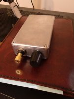
Hi, I'm new here but I wanted to see if anyone could help me. I have a small headphone amp (I think?) that I repaired some parts to get it working again. The chips in it currently are a tle2072cp and two lm6321n.
Does anyone know what this is? I haven't seen anything similar to it. Also what would the proper power supply be? I have it hooked up to a small 12v 2A dc psu currently just for testing purposes since I don't quite know what the correct specs should be.
Thanks and I look forward to being part of this community!
Attachments
The LM6321 is a high speed buffer, the TLE2072 is an uprated version of the well established TL072 dual opamp.
Hard to say what the correct power supply should be without knowing more details. It may well require a dual or split supply of typically -/+12 or 15 volts rather than a single rail supply. The two fuses suggest that is a possibility.
Hard to say what the correct power supply should be without knowing more details. It may well require a dual or split supply of typically -/+12 or 15 volts rather than a single rail supply. The two fuses suggest that is a possibility.
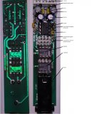
Its difficult working from pictures but that does look like a split rail design.
Just general observations......
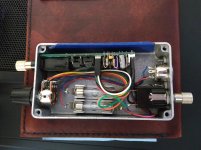
The rectifiers would normally imply that the device is intended to run off an AC supply but in this case there are big question marks......
The caps near the rectifier are to small for that and would mean the rails would be noisy and have ripple present. Also there is no voltage regulation on board, another no-no for small signal circuitry.
All that suggests that the rectifiers are just for polarity protection and the supply should be a clean and stable -/+12 to 15 volts DC.
Also confusing from the pictures is the fact that pin 4 of the TLE2072 should go to the minus rail and pin 8 to the plus rail. The picture showing the components looks logical and fits that arrangement. The other view of the print side doesn't.
Maybe I'm going cross-eyed looking at that but you need to check.
Just general observations......
The rectifiers would normally imply that the device is intended to run off an AC supply but in this case there are big question marks......
The caps near the rectifier are to small for that and would mean the rails would be noisy and have ripple present. Also there is no voltage regulation on board, another no-no for small signal circuitry.
All that suggests that the rectifiers are just for polarity protection and the supply should be a clean and stable -/+12 to 15 volts DC.
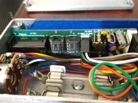
Also confusing from the pictures is the fact that pin 4 of the TLE2072 should go to the minus rail and pin 8 to the plus rail. The picture showing the components looks logical and fits that arrangement. The other view of the print side doesn't.
Maybe I'm going cross-eyed looking at that but you need to check.
For the picture in Post #3, did you mirror the bottom view by any chance?
The LM6521's pinout is:
Pin 2: Input
Pin 6: V+
Pin 7: Output
Pin 1,4,5,8: V-
Looks like it was designed for ±15 to ±18 V rails. You can find the data sheet here:
http://www.electronica60norte.com/mwfls/pdf/LM6221.pdf
Tom
The LM6521's pinout is:
Pin 2: Input
Pin 6: V+
Pin 7: Output
Pin 1,4,5,8: V-
Looks like it was designed for ±15 to ±18 V rails. You can find the data sheet here:
http://www.electronica60norte.com/mwfls/pdf/LM6221.pdf
Tom
The power supply section of the forum perhaps...
Or here: Power Supply for Preamps
You can also look up the LM317 and LM337 regulator pair. There are tons of supplies based on those.
Tom
Or here: Power Supply for Preamps
You can also look up the LM317 and LM337 regulator pair. There are tons of supplies based on those.
Tom
Last edited:
Here is what I would do if you are unsure.
1/ Remove all three IC's.
2/ Connect up a dual rail supply made from two 9 volt series connected batteries. The centre point of the batteries is the zero '0' point.
3/ Measure the DC voltages on the supply pins of the empty IC sockets to determine which way around to fit the IC's. Pin 8 should have plus 9 volts and pin 4 should have minus 9 volts. All voltages measured from the centre point of the batteries.
4/ Use the same method for the remaining IC's to determine the correct way around to fit them.
")
- Status
- This old topic is closed. If you want to reopen this topic, contact a moderator using the "Report Post" button.
- Home
- Amplifiers
- Chip Amps
- Small chip amp identification and help