Somehow I'm only managing to send the circuit into oscillation in this format.
I don't see a minimum gain for stability spec, so let's assume x21 is ok.
If the nfb resistor to ground is 750R, then there should be a 7.5k
resistor between pins 6 and 7, instead of the short shown in your sketch.
Last edited:
You seem to be missing a resistor between pin 6 and pin 7.
The overall gain is set approximately by the ratio of the resistor between pin 6 and 7 and the resistor from pin 7 to ground (via its cap of course). No resistor gives unity gain (and it may not be stable like that).
Thanks, yup that was it!! So I seem to be getting a nice strong gain around 7-8k between pin 6/7 without an intolerable amount of distortion.
On another note, do you happen to know of any good references for an easy DC bias record circuit? For some reason I am only able to find AC bias schematics. I know DC bias is much lower quality but I think I need to stick with DC because I can only use a 9v DC wall adaptor for my purposes.
I don't see a minimum gain for stability spec, so let's assume x21 is ok.
If the nfb resistor to ground is 750R, then there should be a 7.5k
resistor between pins 6 and 7, instead of the short shown in your sketch.
Haha that's pretty funny as I had also arrived at 7.5k by just listening and finding the highest gain without a ton of distortion. Thank you.
Since this circuit is really susceptible to ground hum and RF is it ok to use a 12v DC power adaptor that ties earth ground to neutral? I have done some tests with this circuit and it seems to have helped a good deal, not changed any of the pin voltage readings, and seems to not kill it.
Since this circuit is really susceptible to ground hum and RF is it ok to use a
12v DC power adaptor that ties earth ground to neutral?
Try it out, should be ok.
Last edited:
You seem to be missing a resistor between pin 6 and pin 7.
The overall gain is set approximately by the ratio of the resistor between pin 6 and 7 and the resistor from pin 7 to ground (via its cap of course). No resistor gives unity gain (and it may not be stable like that).
If I place a 50K pot in place of the 7.5k is there a way to possibly use only this pot to turn the volume completely down? As you had mentioned "off" would be unity gain in this case, so I'm assuming no dice?
I'm leaning towards 50K because the distortion available is pretty nice.
If the eq is earlier in the circuit, there's more headroom. If the eq is later in the circuit, there's less noise.
Lower supply voltage gives less headroom.
If the eq is in the first stage, you could connect the recording tape head to that output,
instead of going through the second flat stage, if the first stage's gain is enough.
Really good to know! I have three questions about this. It seems as though introducing the second flat gain stage removed some HFs and made everything a bit muffled. Is that common and is there a common "makeup" of high frequencies remedy?"
Also, if I'm using a line level signal in conjunction with a DC bias (approx. 80 khz) would I normally need to go through something like a single pre-amp stage with NAB?
Lastly, when adding DC bias into the record head I would go post pre-amp and then add some caps and resistors to block the DC from going back into the pre correct?
Thank youuuuu
If I place a 50K pot in place of the 7.5k is there a way to possibly use only this pot to turn the volume completely down? As you had mentioned "off" would be unity gain in this case, so I'm assuming no dice?
I'm leaning towards 50K because the distortion available is pretty nice.
You can not reduce the gain below unity (a gain of 1) for this configuration. A 50k pot would allow the total gain to be varied but you could well find that there is a minimum level beyond which things turn ugly and the circuit starts oscillating.
You can not reduce the gain below unity (a gain of 1) for this configuration. A 50k pot would allow the total gain to be varied but you could well find that there is a minimum level beyond which things turn ugly and the circuit starts oscillating.
Yea that is what's going on so I'll have to figure out the minimum Ohms before oscillation on the pot and place a limiting resistor I suppose?
That is about all you can do really.
If you did have a specific gain in mind then there is a trick we can use to stabilise the opamp but it would be trial and error and would really need an oscilloscope to observe the effects.
If you connect a resistor between the two opamp inputs then that allows you to use a lower gain while 'fooling' the opamp into thinking its working at higher gain.
The additional resistor doesn't alter your set gain.
Noise Gain vs. Signal Gain | Analog Devices
You can not reduce the gain below unity (a gain of 1) for this configuration. A 50k pot would allow the total gain to be varied but you could well find that there is a minimum level beyond which things turn ugly and the circuit starts oscillating.
Actually I was mistaken, at above 47k on the 50k pot I get into oscillation/RF bleed maybe?? At least it has this RF type sound to it. I added a 47K in parallel and and that took care of it.
However, when I attach the remaining leg of the pot to ground oscillation will still begin around 40k on the pot. What is happening here? Pot should be ungrounded?
It is hard to say for sure what is happening. When dealing with a high gain circuits you will find the layout and wiring becomes quite important to maintaining stability.
If the pot is a metal bodied one then ground the outer metalwork may well help stray pickup.
Ok cool, I'll play with that. Do you think it's a problem to leave the pot ungrounded or should that extra leg be tied with the center leg?
I was messing with placing a resistor between the two inputs as you mentioned while the cassette was playing back and it actually ended up recording some saw wave feedback to the cassette tape when I played it back again haha! aka the cassette was playing back and recording through the same head
")
If it is a traditional metal pot then try grounding the body. The third leg can be either left floating or tied to the middle one, it doesn't really matter electrically, and it shouldn't affect any stray pickup either.
If in doubt try both methods, its only a seconds job to tag them together.
Have you considered using a more conventional opamp ?... these dedicated consumer types aren't always very amenable to incorporating into other circuits and can be temperamental and finicky to get satisfactory results from them.
Although they are basically an 'opamp' they are often designed specifically for one specific consumer application such as a tape head preamp.
Yea I just like this gritty sound
Guessing I could get similar gritty sound from something else but pretty happy already!
If it is a traditional metal pot then try grounding the body. The third leg can be either left floating or tied to the middle one, it doesn't really matter electrically, and it shouldn't affect any stray pickup either.
It's actually mostly plastic so I suppose should be good thx.
I have been attempting to create this bias erase circuit (attached) and it burns up my pnp and npn every time. Im using BC337 and BC327 as stand ins. I would guess that wouldn't cause the issue? Also just get more crazy osc as they die.... Does it matter that I'm using a bipolar 1uf in place of the ceramic 1uf to ground in this case?
I'm attempting to use a regular mono playback head to erase with. Not sure if that is where my problem lies creating some feedback and burning out both transistors?
Attachments
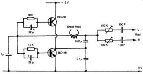
The characteristics of the erase head are a fundamental part of the original design with everything being designed around it. So differences in self inductance, DC resistance and so on will all drastically alter things.
It is possible the 1uF could play a part. A ceramic cap is ideally suited due to its low losses at high frequencies. A film cap should OK as well... but all that assumes the design suits the head you are using... which tbh it probably doesn't.
It is possible the 1uF could play a part. A ceramic cap is ideally suited due to its low losses at high frequencies. A film cap should OK as well... but all that assumes the design suits the head you are using... which tbh it probably doesn't.
- Status
- This old topic is closed. If you want to reopen this topic, contact a moderator using the "Report Post" button.
- Home
- Amplifiers
- Chip Amps
- Squeezing maximum gain from one dual op-amp?