Hello,
I need to make preamplifier for my DIY STK442-090 amplifier.
It plays good, but I know that it can go way louder.
Now I have few ICs and I want to know which one would be the best and also another factor is quantity of external components needed because I will be making it on prefboard.
I have:
BA4558N
4558D
KA4558
I have at least two pieces each.
Another thing is I would like to make preamplifier that will give 12dB boost, because I have pro level audio power amplifier that has +4dB input and I need to connect it to -10dB input.
What about that one?
Thank you for help!")
I need to make preamplifier for my DIY STK442-090 amplifier.
It plays good, but I know that it can go way louder.
Now I have few ICs and I want to know which one would be the best and also another factor is quantity of external components needed because I will be making it on prefboard.
I have:
BA4558N
4558D
KA4558
I have at least two pieces each.
Another thing is I would like to make preamplifier that will give 12dB boost, because I have pro level audio power amplifier that has +4dB input and I need to connect it to -10dB input.
What about that one?
Thank you for help!
You need a power supply.
You should use a better audio amp like OPA2134PA or more advanced.
A volume control chip from TI.
Gives a Gain of +20 dB.
Hello,
yes, I know that I will need power supply.
ICs that I listed aren`t good enough? They were used in hifi components...
"A volume control for chip TI" you mean for example PGA2311? I had a look at the datasheet and found out that this is digitally controlled, is there any good alternative that is analog controlled? I really don`t need it to be digitally controlled and this just makes it more expensive to build...
Thank you for help
Last edited:
You can run an opamp from the main amp rails via a simple resistor/zener supply. The 4558 is OK but could be swapped later for something better.
The 4558 is dual opamp so only one device needed for stereo.
So you need a voltage gain of 4 (12db) which is easy using a 10k and 3k3 feedback network.
If you tell us the supply voltage of the main amp then we can work out the power supply details.
The 4558 is dual opamp so only one device needed for stereo.
So you need a voltage gain of 4 (12db) which is easy using a 10k and 3k3 feedback network.
If you tell us the supply voltage of the main amp then we can work out the power supply details.
Hello,
In that case I will use a socket so I can swap it later if needed.
Power supply for the main amp is 31-0-31vdc, but I will add 12vdc supply because I need it for VU meter and I have transistor that have wires for 31-0-31vdc and 12vdc...
I need input signal gain between a laptop and power amp (this is another power amp for PA not the first one). So I guess this is the voltage gain right? Can I get more information on that? For that one I would like it to sound good, because the power amplifier sounds amazing (Zeck PT7 2 x 450w @ 8ohm)
Thank you
Last edited:
Well the opamp can be fed from two resistors (one for each rail) of 1500 ohms and with a 12 or 15 volt zener to ground to stabilise each rail. A classic resistor/zener shunt.
For a low current VU circuit you could also use a standard 12 volt regulator running off the 31 volt rail. In fact that would be perfect for the opamp as well. The negative 12 rail would still be the resistor and zener.
For a low current VU circuit you could also use a standard 12 volt regulator running off the 31 volt rail. In fact that would be perfect for the opamp as well. The negative 12 rail would still be the resistor and zener.
So this IC needs +12 and -12, not just +12 and GND?
I don`t need 12dB gain for the amplifier with +31-0-31 supply, I don`t know how much gain I do need for that one. I think that I should use a trimmer and adjust it by listening to see how much can I push it before clipping.
I need preamp with 12dB gain for another amplifier. I will have that preamp in it`s own enclosure with it`s own power supply.
So for the second preamp with 12dB gain I can use your schematic, just without r2, r4, zener diodes and 12-0-12 power supply?
So this IC needs +12 and -12, not just +12 and GND?
I don`t need 12dB gain for the amplifier with +31-0-31 supply, I don`t know how much gain I do need for that one. I think that I should use a trimmer and adjust it by listening to see how much can I push it before clipping.
I need preamp with 12dB gain for another amplifier. I will have that preamp in it`s own enclosure with it`s own power supply.
So for the second preamp with 12dB gain I can use your schematic, just without r2, r4, zener diodes and 12-0-12 power supply?
You could make a single rail (0 and 12 volt supply) but it would be a different circuit to this one. This one would not work on single rail.
Do you want a single rail design ?
I can`t get 10uF in the shop near me, can I use any other value?
I see that you used 100k load in the simulation. My amp has 10k input. Should anything in schematic be changed because of that?
The 10uF acts as a DC block and also forms a high pass filter in combination with the impedance of the load.
If your amp has a 10k input impedance then you could use a 22uF cap. When the amp is built and working, be sure to connect the electrolytic cap to match the DC offset of the opamp.
In other words, if the DC voltage at the opamp output pin is positive (for example +100mv) then connect the + of the cap toward the opamp.
If the opamp output pin is negative (for example -100mv) then connect the negative of the cap toward the opamp.
I know this is in chip amp section, but sometimes even 3 transistor preamp can sound amazing...
I will use 4558 ICs because I have them.
Thank you for explanation.You could make a single rail (0 and 12 volt supply) but it would be a different circuit to this one. This one would not work on single rail. <snip>
Yes I would like to make it single rail. Because I will use 12v adapter for second opamp (for my Zeck amplifier)
And I will need 12-0 power supply on my DIY amp anyways for Vu meter and fan.
Is this the right design for single rail?
My professor showed me this design for single rail today. He sad that I need to calculate value for c1, c2, r1 ,r2, but well... I have no idea how to.

EDIT:
I won`t be making preamp for my DIY amplifier because user "PRR" told me to make 2 resistors on the amps circuit smaller and I will get higher gain.
Now I just need "the 12dB boost" one for my Zeck amp
Last edited:
The STK442-090 has gobs of gain in reserve.
Make these resistors smaller.
Thank you for this tip. Looks like I won`t need preamp for this one at all.
So gain will rise linearly? For example 1.8k / 2 = 0.9k, that means double the gain? thank you
Is this the right design for single rail?
My professor showed me this design for single rail today. He sad that I need to calculate value for c1, c2, r1 ,r2, but well... I have no idea how to.
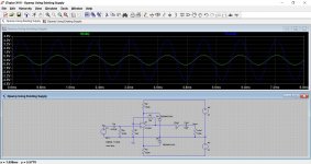
Its basically OK. Give me 5 minutes....
Like this. The one you showed is inverting... which probably doesn't matter unless absolute phase bothers you in the design.
Thank you. I will use this desing. I noticed that u used 100k load. Is the circuit ok for 10k?
Capacitors are all bipolar?
Last edited:
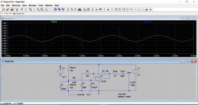
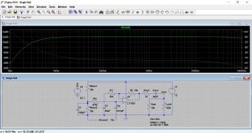
The 100k load is just to correctly terminate the output and to provide a known and reliable path to charge the output cap. A resistor should always be present in that location but it is best to keep the value high.
The output will drive a load down to 600 ohms for most audio opamps. The lower the final load resistance, the bigger the output cap needs to be in order to maintain bass response.
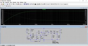
Here is your 10k load added and using 22uF and then 1uF. See how the bass rolls off.
The output will drive a load down to 600 ohms for most audio opamps. The lower the final load resistance, the bigger the output cap needs to be in order to maintain bass response.
Here is your 10k load added and using 22uF and then 1uF. See how the bass rolls off.
Attachments
- Status
- This old topic is closed. If you want to reopen this topic, contact a moderator using the "Report Post" button.
- Home
- Amplifiers
- Chip Amps
- Making preamplifier...