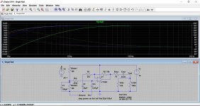
") If you look at the scales you can see that even the 1uF cap is only around -3db down at 20Hz.
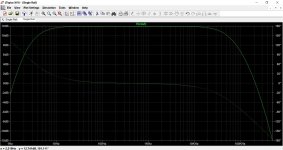
If you look at the scales you can see that even the 1uF cap is only around -3db down at 20Hz. Here are four different values and their effect. Look at the circuit at the bottom to see the value list. We are just looking at 1 Hz to 1kHz now to make it easier to see.
Attachments
That will not be the problem because my amp has turn on delay. I also follow the rule: first turn on everything from source and amplifier as the last one.
What about resistors. Can they all be 0.25w? I know that I will get 0.25w in the store now, anything other will have to be ordered.
What about resistors. Can they all be 0.25w? I know that I will get 0.25w in the store now, anything other will have to be ordered.
I wondered where that had come from as well
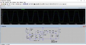
One thing to remember... running on a single 12 volt supply will limit the output to around 3.2 vrms. That means that for a gain of 12db (as we have set it up for) you will not be able to apply more than around 850mv rms to the input. Any more and it will clip.
One thing to remember... running on a single 12 volt supply will limit the output to around 3.2 vrms. That means that for a gain of 12db (as we have set it up for) you will not be able to apply more than around 850mv rms to the input. Any more and it will clip.
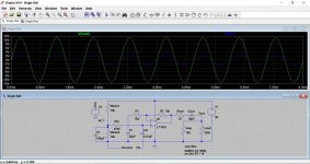
Most common opamps are good for a total supply voltage of up to 36 volts. Always check the data sheets but NE5532, TL072, 4558, OPA2134, LM4562 are all fine on that voltage.
36 volts would allow the output to swing to at least -/+ 15 volts which is over 10 volts RMS.
This is what will happen if you feed the preamp with 2 volts RMS (the maximum output from most CD players). The second image is running on 36 volts.
36 volts would allow the output to swing to at least -/+ 15 volts which is over 10 volts RMS.
This is what will happen if you feed the preamp with 2 volts RMS (the maximum output from most CD players). The second image is running on 36 volts.
Attachments
wow, someting is wrong, here with 11v output voltage, I think that I messed up with something. Here is what I found on the other forum stating that I need only 1.23v
"+4dBu and -10dBV are different standards governing the maximum nominal line voltage of an output signal. 0dBu = ~0.775V. 0dBV = 1V. Positive and negative quantities indicate logarithmic (order of magnitude) differences between a measured signal and the reference signal.
+4dBu is a "professional" standard for equipment and indicates a line voltage of about 1.23V in output signal."
And this is what I found on some other website:
-10dBV = 0.316 volts AC
0.316 volts AC = -7.79dBu
-10dBV = -7.79dBu
+4dBu - (-7.79dBu) = 11.79dB difference
in other words, a -10dBv signal is 11.79dB lower than +4dBu
And this is what I found on another forum:
"As for the laptop jack output, it really depends on whether the jack is set to line-level output (around 0.15V)..."
So I think that I can use this circuit with 12v, because laptops are outputing around 0.15v? I didn`t know that CD players have so much higher output than laptops.
Last edited:
Well I made the preamp and I tried it out with a speaker at the output and it works.
But I get above +2vdc at the outputs.
The 10uF acts as a DC block and also forms a high pass filter in combination with the impedance of the load.
If your amp has a 10k input impedance then you could use a 22uF cap. When the amp is built and working, be sure to connect the electrolytic cap to match the DC offset of the opamp.
In other words, if the DC voltage at the opamp output pin is positive (for example +100mv) then connect the + of the cap toward the opamp.
If the opamp output pin is negative (for example -100mv) then connect the negative of the cap toward the opamp.
So I should turn capacitors around?
I`m powering it from switch power supply (12v laptop adapter) for now.

I`m only missing 1 0,47uF film cap for one channel, I will get it today.
But I get above +2vdc at the outputs.
The 10uF acts as a DC block and also forms a high pass filter in combination with the impedance of the load.
If your amp has a 10k input impedance then you could use a 22uF cap. When the amp is built and working, be sure to connect the electrolytic cap to match the DC offset of the opamp.
In other words, if the DC voltage at the opamp output pin is positive (for example +100mv) then connect the + of the cap toward the opamp.
If the opamp output pin is negative (for example -100mv) then connect the negative of the cap toward the opamp.
So I should turn capacitors around?
I`m powering it from switch power supply (12v laptop adapter) for now.
I`m only missing 1 0,47uF film cap for one channel, I will get it today.
Last edited:
I'm pretty sure a laptop will put out a lot more than 0.15 volts from its line out socket when the volume is turned up.
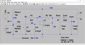
You need to check the voltages on the opamp to confirm all is OK.
Measuring from ground and you should have the power supply voltage on pin 8 (whatever value of supply you have chosen).
ALL the other pins should be at approximately half this voltage.
It is normal to see a little DC voltage on the output (after the cap) for a few seconds as the cap charges up.
With a single rail design there is never any doubt over cap polarity. I have marked them on the diagram together with the voltages you should see if you are running on 12 volts.
Also typical CD player output voltages.
Attachments
Hello,
Cout capacitors were turned wrong way. I have 0dc at the outputs now.
When I connect multimeter to input I get 100mV DC that stars to fall when I connect multimeter. It falls to about 12mV DC.
Is this anything that I should worry about?
What kind of power supply do you suggest for this preamp? Traditional regulated would be beter than switching one right?
What are the best direct swaps of 4558 for this circuit, I want to know so I can swap it in the future.
I will connect it to the amp and start rising volume slowly to see if I have to much gain, I just need to buy connectors for input and output.
Thank you
EDIT:
I got the connectors and tested it and it works good, gain is just right, it doesent sound like it`s clipping. Power amp plays loud and clear
After the holidays I will take it to school to take a look at the output with osciloscope.
Only thing that I would like to fix if it`s possible is loud buzz with no source connected and it`s picking up alot of gsm signals when connected to phone.
Last edited:
Wrongly fitted caps would give some DC due to leakage. So that's one thing fixed
If the input cap is a film type then there is no problem in seeing the 100mv. It is just stray pickup. If the input cap is an electrolytic then it must be fitted with the 'plus' to the opamp.
The two obvious choices for the opamp are an NE5532 or a TL072. There are dozens more but those are the two to try.
The stray pickup is mainly down to the high input impedance (a good thing) and using the preamp with the input floating isn't really a valid condition.
There are two things you can do.
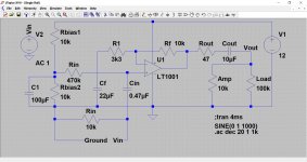
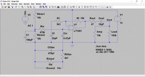
1/ Add a resistor as shown here.
2/ Add a resistor and filter.
The filter gives a nice roll off above the audio band.
If the input cap is a film type then there is no problem in seeing the 100mv. It is just stray pickup. If the input cap is an electrolytic then it must be fitted with the 'plus' to the opamp.
The two obvious choices for the opamp are an NE5532 or a TL072. There are dozens more but those are the two to try.
The stray pickup is mainly down to the high input impedance (a good thing) and using the preamp with the input floating isn't really a valid condition.
There are two things you can do.
1/ Add a resistor as shown here.
2/ Add a resistor and filter.
The filter gives a nice roll off above the audio band.
Attachments
- Status
- This old topic is closed. If you want to reopen this topic, contact a moderator using the "Report Post" button.
- Home
- Amplifiers
- Chip Amps
- Making preamplifier...