Hi
New to DIYAUDIO, I have zero exterience with component level electronics but have been obsessing over building my own amp for ages.
The untimate goal is to have an activly filtered 2.1 system so am starting with a 4 chhannel amp.
Was going to go with a kit but have read stories about fake components, so have purchased 4 bare mono LM3886 PCBs with 2 power supply boards.
The boards are pretty self explanatory even for a complete novice like me so i have easily been able to find the relevant resistors and electrolytics.
However i have a few questions that the seller has been unable to answer, possibly due to a language barrier, and I’m hoping someone on here may be able to help.
The boards come as a package 1 power supply board and 2 LM3886 boards (i ordered 2 packs), I’m assuming I just connect the two boards in parallel from the power supply?
Am I able to connect both power supplies to the same transformer or will I need 2.
Any preference as to the type of the smaller capacitors 0.1uf and 0.01uf on the power supply, all I know from the screen print on the board is that they are not radial.
And for later in the build, what is the best way to split the channels eg, 1 power supply each for L and R, or 1 power supply each for high and mid? I’m leaning towards L and R.
New to DIYAUDIO, I have zero exterience with component level electronics but have been obsessing over building my own amp for ages.
The untimate goal is to have an activly filtered 2.1 system so am starting with a 4 chhannel amp.
Was going to go with a kit but have read stories about fake components, so have purchased 4 bare mono LM3886 PCBs with 2 power supply boards.
The boards are pretty self explanatory even for a complete novice like me so i have easily been able to find the relevant resistors and electrolytics.
However i have a few questions that the seller has been unable to answer, possibly due to a language barrier, and I’m hoping someone on here may be able to help.
The boards come as a package 1 power supply board and 2 LM3886 boards (i ordered 2 packs), I’m assuming I just connect the two boards in parallel from the power supply?
An externally hosted image should be here but it was not working when we last tested it.
Am I able to connect both power supplies to the same transformer or will I need 2.
Any preference as to the type of the smaller capacitors 0.1uf and 0.01uf on the power supply, all I know from the screen print on the board is that they are not radial.
And for later in the build, what is the best way to split the channels eg, 1 power supply each for L and R, or 1 power supply each for high and mid? I’m leaning towards L and R.

Go thru these photos:
 LM3886 based DIY amplifier <a href="[url]https://youtu.be/VIE3igkNbO8" rel="nofollow">The amp on YouTube</a>[/url] by Michael van den Born, on Flickr
LM3886 based DIY amplifier <a href="[url]https://youtu.be/VIE3igkNbO8" rel="nofollow">The amp on YouTube</a>[/url] by Michael van den Born, on FlickrStereo Build:
You can take two sets of power triplets from the PSU board.
One set to each amplifier.
The two amplifiers and the PSU share a common Zero Volts line and any other connection between these items will create a current loop.
You MUST avoid that.
In addition the XY amplifier boards connect the power ground and the signal ground/return to the Power Zero Volts. That's more potential loops that you need to separate.
4 channel Build:
Much more complicated and you will almost certainly mess up the wiring and end up plagued with interference and come back here asking for solutions.
I do not recommend any more channels than 2 inside an enclosure and that is already twice as complicated as building a mono-block.
I suggest you build an experimental mono-block and learn all the lessons you can from that, BEFORE you work out how to build a 2channel amplifier.
The hole spacing relative to the screen print shows they are radial capacitors.
the XY power board shows 4 capacitors at the bridge rectifier.
This is NOT the correct way to snubber a transformer. Do not fill in these capacitors until you learn how to snubber properly.
The 0.1uF capacitors at the output of the PSU do not do any good. You are as well to omit them.
I think these XY boards are the newer small XY boards. They need a slightly different modification compared to the older larger XY boards.
Read the DIYaudio Threads.
Last edited:
4 channel Build:
Much more complicated and you will almost certainly mess up the wiring and end up plagued with interference and come back here asking for solutions.
Not that there's anything wrong with coming back here to ask questions...
")
If you do insist on having all four channels in one enclosure, I suggest building a dual stereo amp within one enclosure. You'll need four amp boards and two supply boards for this. They can share the power transformer if need be.
As Andrew points out, the more channels you stuff into the box, the higher the risk of trouble.
Definitely build a prototype on a piece of plywood first. I.e. build one amp board and one supply board. Attach a heat sink to the amp and test the two boards together. If you add a regular 1/4 W, 10 Ω resistor in series with each supply lead, you can save yourself some trouble. If you have a wiring error or solder bridge on the amp board that shorts out the supply, the resistors will go up in smoke.
The 0.1uF capacitors at the output of the PSU do not do any good. You are as well to omit them.
True. You will need 2x0.1 uF decoupling on the LM3886, however, as XY forgot to include those. So move those caps to the amp boards.
For the amp, you will need 2x0.1 uF (minimum) or 2x1.0 uF X7R ceramic caps to bypass the amp chip. I also suggest replacing the power resistor on the output with an inductor (0.7-1 uH) in parallel with a resistor (1.5-2.2 Ω) for better stability.
I've measured the XY Kit, by the way. You can find the measurements here: XY LM3886 Kit Review & Measurements then compare with my LM3886DR here: LM3886 Done Right
I also suggest reading through my Taming the LM3886 article series here: Taming the LM3886 Chip Amplifier
It should give you quite a few ideas for how to hack the XY board to get a bit more performance out of it - or at least avoid instability.
Tom
Last edited:
@Hardwarejunkie
This is very interesting, I have a bunch components on order with a very similar LM3886 idea. I was thinking about separating each channel completely and using pre-bought power supplies to start with (my soldering skills are still, er, developing)
My experience is with assembling PC's mainly and I always whack everything together and test it outside the enclosure and was planning to exactly that also.
Really looking forward to tracking your progress, do you have good soldering skills?
Chunks
Wow! Thanks for the massively constructive replies! I see i have a lot to learn, not so enamoured with PCBs I’ve ordered now. I did a bit of research on snubberizing and now understand what it is, but I’m a long way off being able to do it myself. So think I’m going to attempt to copy Carlos’ snubberized PSU onto some perf board, maybe knock up one of the PCB’s to see if I can spot the difference. I’ll post some pics once bits start turning up.
The completed amp in the pics in post#3 has the mains connectors to the switch and input socket uninsulated. It makes me shudder!
Expand that over-large image. On the switch, I can see clear insulation over the uninsulated crimps. On the power inlet, I think I see clear-stuff, but I would have to feel it
 to be sure.
It also does not have a safety earth connected.
There are some places where no safety-ground is supplied in homes. In those lands it is customary to use 2-pin cords even if the 3-pin inlet connectors are used. I would agree that the 3-pin inlet should be chassis bonded, just in case it moves to a place where full safety-ground is available.
And it could be "anti-hum ground-lift", common in home hi-fi, though dubious safety, especially in DIY.
Last edited:
I'd be more concerned about the lack of safety ground than any sliver of terminal that may/may not be covered by heat shrink tubing. The ground terminal on the IEC inlet is clearly floating.
I also question the practice of bending the leads on the LM3886. While it makes for a convenient way to mount the board to the heat sink, it will put undue thermal stress on the leads. The package was designed the way it is for a reason...
Tom
I also question the practice of bending the leads on the LM3886. While it makes for a convenient way to mount the board to the heat sink, it will put undue thermal stress on the leads. The package was designed the way it is for a reason...
Tom
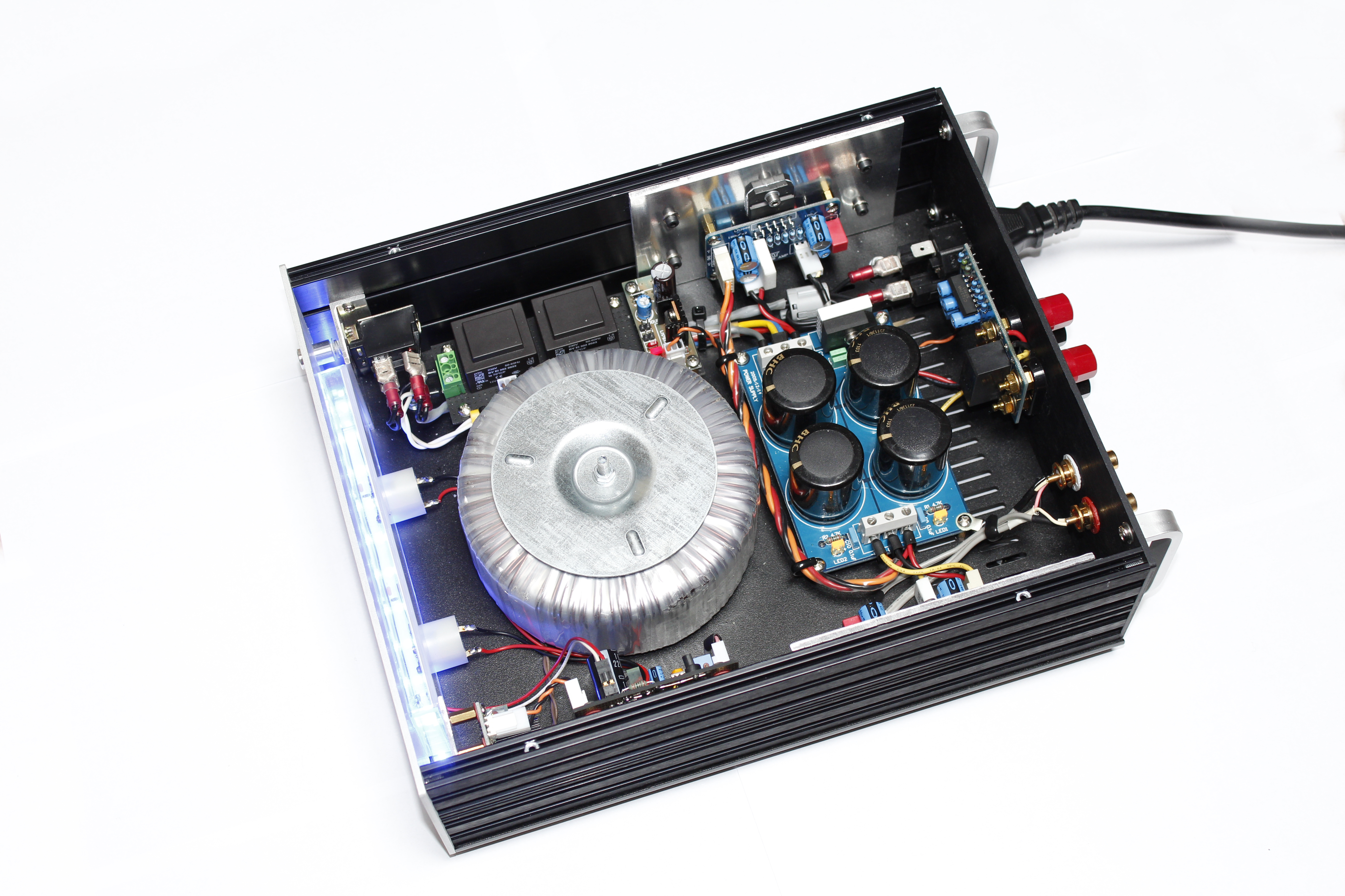
So, I have taken some advise, done a lot of reading, and decided to lower my expectations a bit. I have all but completed a stereo power amp. Its nowhere near as pretty as most on this forum, probably mostly because the case is in the small side.
I modified the power supply a bit, I saw someone had bypassed the large capacitors on the underside of the board so shamelessly stole that idea. I also included snubbers using the LED positions on the circuit board.
I have not yet modified the amp boards other then increasing the capacitance of of C4 a little, and using a star earth instead of the speaker grounds on the boards. not had it playing properly yet as waiting for the correct sized drill bit to mount the chips to the heat sink.
An externally hosted image should be here but it was not working when we last tested it.
An externally hosted image should be here but it was not working when we last tested it.
An externally hosted image should be here but it was not working when we last tested it.
Your picture links seem to be broken, at least I can't see anything.
But I'm interested in the outcome of this, I have a similar project going on with 3 of those XY boards, two for main channels and one for sub. I'm doing active crossover with miniDSP, and these are all going to the same case and all powered from the same PSU... I think I'm asking for trouble with a setup like that, but we'll see how it all plays out
But I'm interested in the outcome of this, I have a similar project going on with 3 of those XY boards, two for main channels and one for sub. I'm doing active crossover with miniDSP, and these are all going to the same case and all powered from the same PSU... I think I'm asking for trouble with a setup like that, but we'll see how it all plays out


- Status
- This old topic is closed. If you want to reopen this topic, contact a moderator using the "Report Post" button.
- Home
- Amplifiers
- Chip Amps
- Absolute beginners LM3886 4 channel amp build