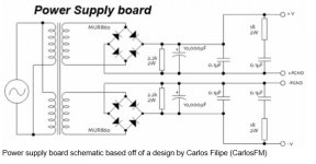
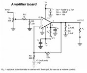
I am rounding up the parts for an LM3886 chip amp build. The BOM calls for a number of 0.1uF 63V capacitors decoupling/snubberizing/Zobel. The original BOM calls for polypropylene film box caps. The fit on the board is very tight not allowing for much dimensional deviations and so finding proper parts that are available in the US has been difficult. How important are the use of PP film caps in these functions vs another material like polyester? In the attached schematics they are in the PS as labeled and on Cs/Cs/Cz on the amp board.
Thanks,
George
Thanks,
George
Attachments
Last edited:
Polyester is fine for these applications, which in reality are pretty non demanding in the big scheme of things ")
If the design was RF rather than audio, or if there were extremely fast repetitive rise times involved then you might be looking to make specific choices... but decoupling and Zobel network duty is all cooking grade design. Use what fits and what is cost effective.
If the design was RF rather than audio, or if there were extremely fast repetitive rise times involved then you might be looking to make specific choices... but decoupling and Zobel network duty is all cooking grade design. Use what fits and what is cost effective.
George,
What is the lead spacing? Try Wima MKP4 at Mouser. Search for:
MKP4D031002D00KSSD
MKP4D031003C00JSSD
5mm pitch, 5mm x 7.2mm body footprint.
George,
What is the lead spacing? Try Wima MKP4 at Mouser. Search for:
MKP4D031002D00KSSD
MKP4D031003C00JSSD
Thank you, your suggestion sent me back to the PCBS where I just noticed that ther are additional through holes that allow for 7.5mm pitch. Open your eyes grasshopper and see what lies before you.
George
Sorry, did not notice they are out of stock until April 2018.
How about this one?
MKP2D031001F00JO00 WIMA | Mouser
How about this one?
MKP2D031001F00JO00 WIMA | Mouser
I think this is the one used by chipamp.
BFC241641004 Vishay / BC Components | Mouser Europe
BFC241641004 Vishay / BC Components | Mouser Europe
Make Cs 4.7uF/100V X7R. Such caps were not easily available when the datasheet was written but since they are now we might as well use them.
Cz can be mkt without any worries. Don't waste money on a mkp there.
Btw, your schematic is incomplete. You are missing the network in // with the feedback resistor (Cf-Rf2 in the datasheet) and one cap in between the + and - inputs (Cc). The single supply schematic is strangely more complete than the dual supply one in the datasheet.
You might also want to add an input cap (safer if you don't have an offset protection) and increase the feedback capacitor to 100uF.
Last edited:
I think this is the one used by chipamp.
BFC241641004 Vishay / BC Components | Mouser Europe
Thanks. That's the closest offering from BC to the original blue box caps but they changed the width.
George
The 1r0 snubbers are in the wrong place on the output of the PSU.
They should be across the transformer secondaries.
DF said
DC block on the input missing. (22k suits either 4u7F BiPolar, or two 10uF back to back)
RF attenuation on the input missing. (1k0 suits 330pF to 1nF across the 22k)
DC block on the NFB lower leg far too small. (680r suits 220uF, or 330uF)
00940 said
They should be across the transformer secondaries.
DF said
remove the 0.1uF, it can only increase the risk of ringing.If you omit the 0.1uF bypass caps in the PSU then you might not need the PSU snubber.
DC block on the input missing. (22k suits either 4u7F BiPolar, or two 10uF back to back)
RF attenuation on the input missing. (1k0 suits 330pF to 1nF across the 22k)
DC block on the NFB lower leg far too small. (680r suits 220uF, or 330uF)
00940 said
read the datasheets again and ask if you don't understand.You are missing the network in // with the feedback resistor (Cf-Rf2 in the datasheet) and one cap in between the + and - inputs (Cc). The single supply schematic is strangely more complete than the dual supply one in the datasheet.
Last edited:
Yes, across the ~~ terminals since this is effectively across the secondary.Snubbers are placed across switching elements, often across rectifiers
because he did not know what the effect of adding the low esr cap to the inductance in the nearby circuit when a step change in current was imposed., I presume they were adopted by the gainclone community due to the minimal smoothing used in the design and their small size?
There is a certain school of 'design' which always adds a 'bypass' across every big cap, and scatters 'snubbers' liberally around (yet sometimes avoiding the places where a snubber might do some good). In some cases, the otherwise unnecessary snubbers deal with the harm created by the unnecessary bypasses.
I may need to rethink my approach. I chose the Chip Amp.com boards as my starting/learning point for my first gain clone build. The schematics I provided are those boards and BOM. After reAding these comments it appeRs that this design is not held in high regard, although I am learning a lot. I have a few other boards, maybe I'll post the schematics and see if any of those get better reviews.
George
George
it is often possible to add components or change components to a pre-made PCB.
Have a good look at your PCB and see what mods/additions are feasible. This is a really good learning experience in becoming familiar with the PCB, it's layout, what each component does and what is possible to change in someone else's design.
Only where all your desired and some of the NEEDED mods are impractical do you throw the PCB away.
- Status
- This old topic is closed. If you want to reopen this topic, contact a moderator using the "Report Post" button.
- Home
- Amplifiers
- Chip Amps
- Chip amp decoupling/snubberizing caps