Well the mute circuit ensures that the output is kept at the voltage present at the gnd pin. Since it's pretty much the same as the input voltage bias, the amplifier output will continue to be defined by C11*(R2||R5) once the amp unmutes. Or am I missing something ? I agree though that it would be more elegant to unmute only when all the proper operation points are correctly established.Actually, not necessarily. You'd need C11 to be large and the charging time for the mute circuit (so C27*R8) to be significantly longer than C11*(R2||R5). Recall that once the IC un-mutes, the voltage on its ground pin becomes irrelevant. See: LM3886 chip amp grounding.
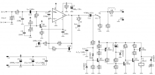
You'll have to ask to the guys who drew the datasheet, I just followed their typical app circuit. When I drew the pcb, I really intended a quick solution and didn't think a lot about what was in the datasheet. Your suggestion makes a lot of sense though ...I'm curious why you don't take the GND reference for the input on the emitter of T1, though.
Speaking of T1: I would add a load from its emitter to GND. Emitter followers are not fond of light loads and the only load it "sees" is some fraction of a base current from the LM3886.
AHA! So they didn't figure it out properly for for single ended!The mute circuit works fine. It regulates the output of the IC to the voltage on the GND pin. If that voltage is not the same as the speaker negative terminal voltage, you'll get a plop in the speaker when the IC un-mutes. Also, the output cap needs to charge on start-up, which will cause a pretty significant plop in the speaker, so adding an anti-plop relay is a good idea.
Personally, I use the LM3886 in a split supply (i.e. Vsupply = ±V) scenario. I have never had an issue with turn-on plop caused by the LM3886.
The mute circuit is useless for DC protection. If you need that, you'll be adding a relay. In that case, you might as well delay the turn-on of the speaker as well. For a single supply system, I'd definitely encourage the use of a relay, both for DC protection and for anti-plop.
Tom
That last bit is fair comment. I thought the way the mute circuit worked it pretty much disables the input stage current that may or may not stop it from plopping at the output....
Yes, I prefer split rails but this chap has done his single ended to suit his supply so that suggestion seemed off the cards.
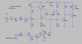
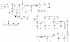
Ok, here the schematic with complete DC protection. Belt and suspenders approach. The dc protection and muting delay are taken from the esp33 project.
I also added a load for the transistor driving pin7 following Tom's suggestion.
I'm afraid I'll need to add about 1cm to the length of the board if I want to stay with through hole parts.
Using a 48V smps adjusted to 50V, it'll make 30W into 8R, a bit less than 60W into 4R. For a single amp, that means a 48V/2.5A smps for 8R, twice that for 4R. Well at least if you want full continuous output power. The meanwell lrs-150-48 seems like a good option in real life.
Attachments
Ok, that wasn't completely thought through. If the cap falls short, there will be 24Vdc across the 68R R12. That's 8W of heat. So R12 has to be increased to at least 330R. That's still 1.8W but increasing R12 too much will require to increase the startup delay quite a lot.
I suspect you can minimize the amount of circuitry in the protection/delay circuit by turning some of the NPNs to PNPs and vice versa. At least casual observation reveals that you could put the relay in the collector of Q2, thus saving Q1 and associated components. You don't need D2. I don't think D4 will ever turn on, so get rid of that.
Before committing to a PCB layout, I'd toss the circuit into your favourite spice simulator and run a couple of simulations. Look at start-up. Also look at performance at LF, say rail-to-rail 20 Hz (and below). See when the DC protection starts to trip.
Tom
Before committing to a PCB layout, I'd toss the circuit into your favourite spice simulator and run a couple of simulations. Look at start-up. Also look at performance at LF, say rail-to-rail 20 Hz (and below). See when the DC protection starts to trip.
Tom
You're certainly right on Q1/Q2. Removing more transistors isn't easy if I want to keep the startup delay baked in.
D2 isn't really necessary. With the values of the schematic attached here under, the dc protection will kick in after 10ms. D2 should help the relay to engage a bit faster according to the article on esp's website. D4 is indeed never conducting as far as I can see in sims.
Startup delay is about 4s. The dc protection doesn't engage with +/-24V at 20hz (it does at 11hz) and is reasonably fast (10ms, not counting the relay switching time, for a sudden 24VDC offset).
I added a led to signal a fault while I was at it.
edit: the names refer to the schematic in post 43. The schematic here under isn't consistent wrt names. Sorry for that.
Attachments
Last edited:
Cool! I think you might be able to cut one transistor out of the circuit by pulling low the base of Q4 rather than Q3, but getting the LED in there at the same time might be a challenge. Meh. One transistor and a resistor or two won't wreck the budget (neither in terms of money nor board area).
The only thing left now is to cut out the relay when the incoming AC fails or is turned off. You can do that by powering this circuit from a separate rectifier (or just a diode) with a small reservoir cap (say 100 uF). You just need the relay to discharge the reservoir cap faster than the amp discharges the main reservoir cap.
Tom
At the risk of adding still more transistors, I'd rather use an AC loss detection trigger as it is a more flexible solution. A typical example would be using an smps for the amp but having AC available from an aux circuit transformer.
Still copying project 33 from ESP (I don't feel like reinventing the wheel on this), it gives the attached schematic. I might have to adjust R14/C3 in real life. The sims results are quite different from the ones suggested by the article. Using a 1uF cap makes the output switch on and off continuously.
Still copying project 33 from ESP (I don't feel like reinventing the wheel on this), it gives the attached schematic. I might have to adjust R14/C3 in real life. The sims results are quite different from the ones suggested by the article. Using a 1uF cap makes the output switch on and off continuously.
Attachments
I like D.Self's loss of AC detector.
It can be set to detect and trigger on one missing sinewave cycle, or to a few missing cycles.
I have it set to one missing and trigger. On mains AC present, it allows the normal delay timer to switch back on. Thus no chattering relays.
It can be set to detect and trigger on one missing sinewave cycle, or to a few missing cycles.
I have it set to one missing and trigger. On mains AC present, it allows the normal delay timer to switch back on. Thus no chattering relays.
Have you looked at start-up? I.e. a slow ramp on V1 in your circuit?
I'm not liking how Q3 needs to be on for the relay to turn off. My concern is that the relay will turn on and off then back on during startup. A simulation will tell you.
This circuit is not unlike a power-on reset (POR) circuit on a chip. You don't know power-on and power-off issues until you've designed one of those ... and a bias circuit.")
Tom
I'm not liking how Q3 needs to be on for the relay to turn off. My concern is that the relay will turn on and off then back on during startup. A simulation will tell you.
This circuit is not unlike a power-on reset (POR) circuit on a chip. You don't know power-on and power-off issues until you've designed one of those ... and a bias circuit.
Tom
I've had a look. There is indeed a small blip at startup as Q4 starts conducting. In sims the voltage across the resistor simulating the relay goes up to 3.5V before being pulled again to 0. On a 48V relay that should be ok. I'm using the schematic of the esp33 as is in a power supply and it works without problems.
The voltage developed across the relay is function of the speed at which the supply rise but depends mostly of the value of R8.
The voltage developed across the relay is function of the speed at which the supply rise but depends mostly of the value of R8.
After being first in vacation, then busy and finally sick, I found the time to revisit this thing.
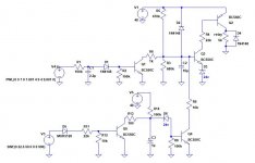
I managed to slightly simplify the dc offset detection circuit. The cost is a slightly more complicated ac-loss detector. It's all fairly basic.
For the dc-offset circuit: R1-C1 are the input filter. R2 allows to tailor the sensitivity of the offset detection. R5-C2 determine the startup delay. Once the voltage at the base of q3 reaches 25.5V or so, q3 turns on and turns on q2, allowing the 48Vdc relay to operate.
For the ac-loss circuit: as long as q5 operates, it keeps discharging c3, keeping voltage at the base of q4 low. When ac disappears, q5 turns off and the voltage shoots up, turning on q4 which shorts out the base of q3. The zener is needed as there's always a small dc voltage at the top of c3.
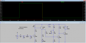
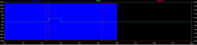
Besides the schematic, I attach a quick sim result to show it operates as it should. Blue is the input of the ac-loss detector, green is the input of the dc-offset detector. Red is the current through the relay. There is a 6.5sec startup delay btw.
I managed to slightly simplify the dc offset detection circuit. The cost is a slightly more complicated ac-loss detector.
It's all fairly basic. For the dc-offset circuit: R1-C1 are the input filter. R2 allows to tailor the sensitivity of the offset detection. R5-C2 determine the startup delay. Once the voltage at the base of q3 reaches 25.5V or so, q3 turns on and turns on q2, allowing the 48Vdc relay to operate.
For the ac-loss circuit: as long as q5 operates, it keeps discharging c3, keeping voltage at the base of q4 low. When ac disappears, q5 turns off and the voltage shoots up, turning on q4 which shorts out the base of q3. The zener is needed as there's always a small dc voltage at the top of c3.
Besides the schematic, I attach a quick sim result to show it operates as it should. Blue is the input of the ac-loss detector, green is the input of the dc-offset detector. Red is the current through the relay. There is a 6.5sec startup delay btw.
Attachments
well done 940.
That implementation is very similar to D.Self's, that I have been using for many years.
It does not suffer chatter due to the delays.
It has delayed ON at start up and after reset following a DC detection.
It has instant OFF on loss of mains and/or DC detect.
The one problem I have found is that at some very low frequency and with high signal level the DC detect gets confused and sends a string of pulses to the the trigger transistor. In practice on a working amplifier I don't find this to trigger spurious triggering. But it is easily demonstrated using a sinewave generator feeding the DC detect.
Not all is quite perfect yet though. A point of problem is the load resistor charging up the output capacitor and how it mixes up with the dc offset protection. It has to be relatively low (<300R) otherwise the delay required gets very long. So what are the options ?
1. using a simple spst relay (or a spdt wired to gnd the speaker as often suggested), the load resistor has to be connected to the output all the time. Which means it has to deal with signal (up to 20vac sinewaves) and fault conditions (48vdc at absolute worst case if both the lm3886 and the output cap die).
2. using a spdt relay - to either connect the output to the load resistor (nc position) or to the speaker (no position) - means that the load resistor doesn't see signal conditions but still see fault conditions.
In any case, that means a 300R 10W resistor... Or I've to get more sophisticated and I'm not sure it's worth it.
In the end, for the load resistor, I decided to go for 3 130r/2w resistors in serie, always connected. If things go completely wrong and 48v end up at the output, they should barely survive without setting anything on fire.
It also came to me that I could use the mute signal for the lm3886 mute pin, rather than relying on a rc filter.
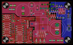
Here is the current shape of the pcb. It is 9*5.5cm big.
It also came to me that I could use the mute signal for the lm3886 mute pin, rather than relying on a rc filter.
Here is the current shape of the pcb. It is 9*5.5cm big.
Attachments
- Status
- This old topic is closed. If you want to reopen this topic, contact a moderator using the "Report Post" button.
- Home
- Amplifiers
- Chip Amps
- Single supply LM3886 layout