I recently had a "pop, sizzle, smoke" incident with my B&K CT600.1 6-zone amplifier.
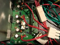
Upon opening the case - found 1 very crispy (and very burnt) LM3886.
So I tried to do some testing before I completely tear-it down and start replacing parts.
What I found was that both Zone 5 & 6 (zone 6 was the obvious dead LM3886) have 35vDC on the outputs. And after removing Zone-6, Zone 5 is running hot enough that the heatsink is getting warm. Not too hot to touch, but the chip is running much warmer than the other 10.
Checked all voltages against the schematic and they all check out.
I have attached the full schematic and with a thorough testing of what I could on the boards - it appears I have a few caps that are leaky and a pair of schottky diodes that are failed/failing.
All other channels check out with 1-2mV on the outputs and comparing all voltage, resistance and diodes with the faulty channels this is what I "think" I need to replace.
Items to replace:
2 - LM3886T (obviously)
D17 & D20 - schottky diodes
C17 & C18 - check as low capacitance (Zone 6 is 85uF and fluctuates, Zone 5 is 95uF and fluctuates)
I was thinking of replacing the BJT's (Q17, Q5 and Q11), since it will be torn apart - just to be safe.
Anything else I might be missing or should check before I order parts and move forward?
EDIT:
Not sure if a moderator can change the title. I got in a hurry and can't edit.
1-2 channels dead on B&K CT600.1
Attachments
Last edited:
I'd look at R5, R6 (series output resistor) as well.
I wouldn't worry about the transistors. They're part of the mute circuit. If the remaining LM3886 works well enough to support mute, measure the voltage on pin 8 of the LM3886. You should see about -3 V under normal circumstances. If that works, the transistors are fine.
Tom
I wouldn't worry about the transistors. They're part of the mute circuit. If the remaining LM3886 works well enough to support mute, measure the voltage on pin 8 of the LM3886. You should see about -3 V under normal circumstances. If that works, the transistors are fine.
Tom
Thanks Tom - I know you are a guru with these LM3886 chips.
I also checked R7 R8, because the +8 and -8 are only giving me +6 -6, but they resistors are 2.26k on the schematic, but banding and measurement shows 1.5k, so I think there has been a few Rev. since my schematic was made.
I checked PIN 8 and for the "bad" channels I get -0.2-0.3mV and even at start-up or power-down it only goes to -1.2mV.
I checked 2 other accessible chips and they are at the same -0.2mV running, but they go from -3.2V down to -0.2mV in about 5 secs after power on. I think that is good, since the mute should be active then.
I also verified on the "fried” channel, C33, C34 appear to both be OL and the other faulty channel they are showing a much higher capacitance.
I checked them - they both are within spec at 2.24kI'd look at R5, R6 (series output resistor) as well.
I also checked R7 R8, because the +8 and -8 are only giving me +6 -6, but they resistors are 2.26k on the schematic, but banding and measurement shows 1.5k, so I think there has been a few Rev. since my schematic was made.
I wouldn't worry about the transistors. They're part of the mute circuit. If the remaining LM3886 works well enough to support mute, measure the voltage on pin 8 of the LM3886. You should see about -3 V under normal circumstances. If that works, the transistors are fine.
Tom
I checked PIN 8 and for the "bad" channels I get -0.2-0.3mV and even at start-up or power-down it only goes to -1.2mV.
I checked 2 other accessible chips and they are at the same -0.2mV running, but they go from -3.2V down to -0.2mV in about 5 secs after power on. I think that is good, since the mute should be active then.
I also verified on the "fried” channel, C33, C34 appear to both be OL and the other faulty channel they are showing a much higher capacitance.
R5, R6 should be 0.1 Ω, 5 W.
R7, R8 are in CH1, 2 which you say are working. Not sure why you're messing with them.
The voltage on the mute pin (pin 8) should be pulled low (-3 V) when the chip is supposed to be active (not muted). If Pin 8 sits at ground (0 V), the output is muted. If you get +35 V out under those conditions, the LM3886 is definitely dead.
C33, C34 are unlikely but not impossible to have fried. I'd replace them with 35 V or 50 V types if you can.
Are you measuring the component values with the parts in the circuit? If so, don't count on getting a good reading as you're measuring the component plus whatever is in parallel with it.
Tom
....I checked them - they both are within spec at 2.24k....I'd look at R5, R6 (series output resistor) as well....
"Series output resistors" are typically *small* Ohms; much less than 8r. Not 2K.
I see R5 R6 as 0.1 Ohm.
Attachments
R5, R6 should be 0.1 Ω, 5 W.
R7, R8 are in CH1, 2 which you say are working. Not sure why you're messing with them.
The voltage on the mute pin (pin 8) should be pulled low (-3 V) when the chip is supposed to be active (not muted). If Pin 8 sits at ground (0 V), the output is muted. If you get +35 V out under those conditions, the LM3886 is definitely dead.
C33, C34 are unlikely but not impossible to have fried. I'd replace them with 35 V or 50 V types if you can.
Are you measuring the component values with the parts in the circuit? If so, don't count on getting a good reading as you're measuring the component plus whatever is in parallel with it.
Tom
Yes I checked R5,R6 in 4-channels, they are all measuring the same.
Sorry about that - got on wrong page (low-power supply) and measured those.
Makes sense, I plan on replacing both.
Thanks for that - I had 250V parts in my cart, 50V should be a little cheaper.
I am, but as much as I'm looking at the schematic I am also comparing to the other channels (and calculating the parallel resistance) to make sure they are similar.
Thanks Tom.
"Series output resistors" are typically *small* Ohms; much less than 8r. Not 2K.
I see R5 R6 as 0.1 Ohm.
I see that now - and I did measure the right ones (and in spec), just confused and put the low-power board measurements.
Thanks for jumping in and highlighting the specific part(s).
Back for some more advice. How hard would it be to take out the zone inputs and just turn this into a 10-channel amp for DSP duty?
As I mentioned before - I'm new to reading diagrams, so the different ground/earth symbols has me confused and all the different connections going across multiple pages.
Trying to figure out what voltage should be going to the mute circuit (highlighted JP3 pin 5/6) and then how to wire an RCA off of the plugs, appears to be Pins 1/9. But when I go to JP4 and JP5 on the Zone board it appears to be different numbering. From there - I'm lost.
I attached what I think are the important parts of the schematic for your ease, but could be wrong.
Any assistance would be appreciated.
Attachments
Converting 6-Zone LM3886 amp to multi-channel DSP amp
Bump - to try and get some possible answers to eliminating the "zones" and using this as a 10 channel amp for a DSP project?
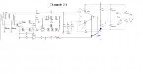
1st page of attachment (I drew in different colors to assist w/routing):
This is the LM3886 and it's mute circuit. Any idea, how I can “tap” into the “1”, “9”, “5 & 6” pins to separate from the zones in this amp? I
get that Pin 1 & 9 are the positive input from the RCA, but I'm missing something, because I get no sound at the moment with them attached to RCA's.
Question(s) –
- what do I connect to pins 5 & 6? Should there be voltage going to the base of Q17 - if so what voltage? I can't see any voltage on those pins with my DMM when it's on, so I'm at a loss.
- do pins 1 & 9 go to center of RCA?
- do I need to ground all the other pins? Or leaving open is ok?
2nd page of attachment:
This is the connector from the LM3886 above (JP3) and it’s associated connector on the 6-zone board.
Bump - to try and get some possible answers to eliminating the "zones" and using this as a 10 channel amp for a DSP project?
1st page of attachment (I drew in different colors to assist w/routing):
This is the LM3886 and it's mute circuit. Any idea, how I can “tap” into the “1”, “9”, “5 & 6” pins to separate from the zones in this amp? I
get that Pin 1 & 9 are the positive input from the RCA, but I'm missing something, because I get no sound at the moment with them attached to RCA's.
Question(s) –
- what do I connect to pins 5 & 6? Should there be voltage going to the base of Q17 - if so what voltage? I can't see any voltage on those pins with my DMM when it's on, so I'm at a loss.
- do pins 1 & 9 go to center of RCA?
- do I need to ground all the other pins? Or leaving open is ok?
2nd page of attachment:
This is the connector from the LM3886 above (JP3) and it’s associated connector on the 6-zone board.
Attachments
Any help would be great, even if it's "you can't do that", or "it's not worth doing".
Figured I'd spend $$$ and time, repurposing what I have, than trying to fix the 2 burned channels, because it appears there is a problem in teh "zones" board now, so no channels are working at this time.
Figured I'd spend $$$ and time, repurposing what I have, than trying to fix the 2 burned channels, because it appears there is a problem in teh "zones" board now, so no channels are working at this time.
Yes, connect pins 1 & 9 to the centre of the RCA.
You also need to connect pins 2 & 10 to the RCA grounds/returns and R61 must not be open.
To unmute the LM use the method in the datasheet. All you need is a resistor and a capacitor.
Don't make any of these connections without removing the existing ones.
You also need to connect pins 2 & 10 to the RCA grounds/returns and R61 must not be open.
To unmute the LM use the method in the datasheet. All you need is a resistor and a capacitor.
Don't make any of these connections without removing the existing ones.
Last edited:
Thansk for that Mark.
Any chance you might know how I could use the mute circuit already there? Such as, putting some voltage (need amount) to pin 5/6 with a jumper? It appears that taking out the "zone" board also took out whatever was needed to use that circuit.
Sorry still very new to this stuff.
Paul
Any chance you might know how I could use the mute circuit already there? Such as, putting some voltage (need amount) to pin 5/6 with a jumper? It appears that taking out the "zone" board also took out whatever was needed to use that circuit.
Sorry still very new to this stuff.
Paul
It is confusing, but this what I have traced so far...
JP1/2/3 (on page 10-12), then go to JP4/5 (on page 13) and these are 2 ribbon cables that attach to either side of the "zone controller" board.
Zone controller board is on page 3 - and are JP9/11.
JP9/11 then goes to (some of all) the 40-pin connectors (JP1-7) on the bottom of the 7 individual I/O daughter boards that exit the rear panel of the amp.
I'm with you - very confusing, because I don't see anywhere a resistor/cap combo and I can't find a voltage on any of these ribbon cables that would be enough to turn-on/turn-off the transitor and make the mute circuit work properly.
This is where my "noob" comes in. I can't measure anything but 2Vdc on nay of those pins, when it's on.
Any idea what voltage it should be sending to Q13, 15, 17 "base" to turn on the transistor.
This should make the mute turn off - correct?
Q13 is a 50V NPN (2N5210) - so can I try feeding it +35V(V+) on the base to see if that "makes the circuit pull down the voltage and turn off mute"?
Any idea what voltage it should be sending to Q13, 15, 17 "base" to turn on the transistor.
This should make the mute turn off - correct?
Q13 is a 50V NPN (2N5210) - so can I try feeding it +35V(V+) on the base to see if that "makes the circuit pull down the voltage and turn off mute"?
I modified the "mute" circuit and it now comes out of mute. Seee attached image, but I cut the on-board mute circuit (R48) and linked Pin 8 to Pin 4 with a 10k, 1/4 watt resistor.
Problem arose - which is now I have ~5Vdc on the speaker outputs.
Did I screw up the circuit, by the way I cut into the mute and added the 10k resistor? NOt sure how, because nothing is connected to JP2's Pin 5 & 6, which is what gave the signal to the mute circuit originally.
I have checked all the resistors, diodes and zeners in two (should be) good channels (#3 & 4), but not sure what to check now that I am getting such high DC on the outputs. Thought I'd check back and see if someone could tell me if a certain capacitor might be more likely to have a proble and cause the DC issues, since I have to unsolder to check.
Attachments
- Status
- This old topic is closed. If you want to reopen this topic, contact a moderator using the "Report Post" button.
- Home
- Amplifiers
- Chip Amps
- B&K CT600.1