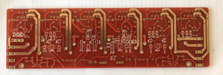
Hi. I recently ordered 6xLM3886 BPA300 pcbs from Jim's Audio. Schematic says that there are OPA2604 used for DC servo and also as a balanced line driver that converts input signal. Unfortunately I can't find exactly these opamps in my area. So the question is, can be some other opamp (like OPA2134) used instead? Should any values of surrounding elements be changed in this case?
I can post schematic if that helps in this case.
Thank you.
I can post schematic if that helps in this case.
Thank you.
Last edited:
 Moved
MovedFor the functionality, yes, you can swap them. That works mit most FET OPamps. The OPA2604 are especally designed for audio though and other OPs will most likely sound differently. An example how different it can be is this YT-video. It does not compensate for the different gain which causes the AD712 to distort (more) but it's IMO still audible (or at least partly) that the OPA2604 got much better details. That is ofcourse depending on the circuit and not 1:1 transferable to other applications. However, it does show there actually are differences between the OPamps.
To substitute the OPA2604, you have to look at other FET OPamps, bipolar ones will not work correctly here since they will introduce DC offset, the servo will definitively not work as intended. I don't have much experience regarding FET OPs replacement in audio, the TL072 and TL082 will work though. As an alternative for OPA2604 it would be better to use special designed OPs for audio like the OPA1679, which is cheap and 'able' FET OP but I don't know about the availability or price in your area (where are you from?).
If you can't get these I would socket the OPs an try with standard (available) FET OPs like the TL082 and swap it later if you aren't satisfied.
The OPA2604 is no longer produced due to problems in production, apparently the later devices degraded and dropped out of spec when used at high supply voltage.
The TL072 is ideal for a servo, and in any case no audio appears at the servo output.
For audio it is actually still a good choice... try it.
The TL072 is ideal for a servo, and in any case no audio appears at the servo output.
For audio it is actually still a good choice... try it.
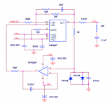
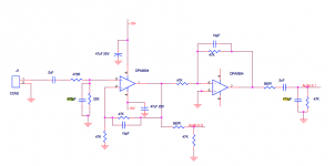
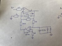
Here are the schematics of one amp block and balanced line driver based on OPA2604.
Thank you for replies. Are any changes to surrounding elements of dc servo needed? I am confused because in TI's AN-1192 application which describes BPA200 circuit different values of those elements and different opamps are used and I thought they might need to be different if I'm going to swap OPA2604 for something else.
By the way, I live in Netherlands
Attachments
Last edited:
A DC servo is self-regulating per definition. That means, this function will stay the same as long as the used OPs are within the intended operation value ranges. The OPs differ in gain, noise, slew rate, maximum voltage etc, so there will be a difference but i.e. gain is not an issue in your case, neither is maximum voltage and DC offset is not an issue originating from the FET OPamps either anyway. That does not mean you can ignore a DC offset check before use though, that should always be done.
The BPA200 works a lot different than the LM3886 gainclone, it is designed as a bridged/parallel bridged amplifier. Following that, ofcourse it looks different and the values have to be different too if you are going to feed multiple ICs (BPA200: four ICs) because the design goals are different in priority. And there are more than just strictly one way (and one set of values) to achieve a desired result.
The BPA200 works a lot different than the LM3886 gainclone, it is designed as a bridged/parallel bridged amplifier. Following that, ofcourse it looks different and the values have to be different too if you are going to feed multiple ICs (BPA200: four ICs) because the design goals are different in priority. And there are more than just strictly one way (and one set of values) to achieve a desired result.
I don't think those chipamp schematics are correct.Here are the schematics of one amp block and balanced line driver based on OPA2604.
Thank you for replies. Are any changes to surrounding elements of dc servo needed? I am confused because in TI's AN-1192 application which describes BPA200 circuit different values of those elements and different opamps are used and I thought they might need to be different if I'm going to swap OPA2604 for something else.
By the way, I live in Netherlands
take away the DC servo loop.
What is left is a 22k feeding back into the -IN node.
The feedback lower leg impedance/resistor is missing?
As shown you have a gain of 1 Follower that will be unstable.
Last edited:
The middle schematic shows two stages:
stage 1 is a non-inverting gain of 2 stage, with DC block on input.
Any DC offset generated in the opamp will be multiplied by 2.
stage2 is an inverting with a gain of 1.
It has a DC block on the output.
When you take the output from stage 1 and from stage 2 the total gain becomes 4rimes the input voltage (+12dB)
The two outputs are not balanced.
You should have identical components on the outputs as seen from the loads.
I don't think those chipamp schematics are correct.
take away the DC servo loop.
What is left is a 22k feeding back into the -IN node.
The feedback lower leg impedance/resistor is missing?
As shown you have a gain of 1 Follower that will be unstable.
The middle schematic shows two stages:
stage 1 is a non-inverting gain of 2 stage, with DC block on input.
Any DC offset generated in the opamp will be multiplied by 2.
stage2 is an inverting with a gain of 1.
It has a DC block on the output.
When you take the output from stage 1 and from stage 2 the total gain becomes 4rimes the input voltage (+12dB)
The two outputs are not balanced.
You should have identical components on the outputs as seen from the loads.
Indeed these schematics seem odd. I wonder if actual PCB is correct. Parts in balanced line driver can be altered to have equal gains (of 1 I guess) on both lines. But if feedback lower leg resistor is missing from LM3886, then it makes this PCB just garbage.
Will check it after PCBs will arrive.
Also I was going to get rid of DC block capacitors both in input and output of balanced line driver.
I’ve checked BOM list supplied together with schematics and it includes 6 1k resistors that cannot be seen on schematics. Seems that this is missing feedback resistors so I hope that actual PCB is ok.
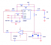
I also have another question. Why DC servo opamps on schematic 1 and schematic 3 are in different polarity? These blocks seem identical even though one of them drives “+” signal and another one drives “-“ signal so why dc servo is in different polarity? I thought all blocks have to be identical since they are driver by the balanced line.
Sorry, I’m just a hobbyist so I might ask stupid questions.
Both chipamps are non-inverting...................Why DC servo opamps on schematic 1 and schematic 3 are in different polarity? These blocks seem identical even though one of them drives “+” signal and another one drives “-“ signal so why dc servo is in different polarity? I thought all blocks have to be identical since they are driver by the balanced line..................
Both take a feedback from output to -IN.
Both take the DC servo feed to the -IN.
The polarity (non-inverting) of the DC servos should be the same.
Check the PCB when it arrives.
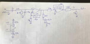
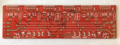
PCBs arrived yesterday finally so I went down them and have drawn the actual real schematics. It is in attachment. It appeared to be way better than the schematics supplied earlier.
So it does have additional feedback resistor on LM3886s so it's not unity gain, that's good.
Also all 6 blocks are the same including servo circuits so that's also good.
Also outputs of both lines of balanced line driver are the same so that's also good.
However I still have several different questions so I'll try to ask them all together.
1. Output of DC servo circuit has 100k resistor but AN-1192 for LM3886 says that this resistor should be 10 times larger than feedback resistor which is 22k so this means that it should be 220k. Is there a reason why it could be made smaller or it's better to stick to datasheet recommendations?
2. The same documentation (AN-1192) uses LF412 op amps for dc servo circuits and it seems that they fit for this purpose really well because they have very good dc performance. So I guess it would be good to use those op amps and values of surrounding elements according to TI's docs?
3. For balanced line driver does it make sense to use "audio" op amp like OPA2134? If I'll use JFET OPA2134 which has low dc offset can the balanced line driver output 2uF caps be omitted? Or maybe it's worth to use bipolar OPA1602 which has lower noise but keep those caps?
Minor:
4. I saw in some schematics that OS-CON capacitors are used for the power supply decoupling of op amps? Does it make sense to use those or it will be useless and it's better to stick to cheaper Panasonic FMs?
That's a lot of questions but I really appreciate is you guys can help me out with those. Thank you.
Attachments
1/ Making it smaller increases the range over which the servo can operate. A good test is to measure the DC voltage on the output of the servo opamp. If it is getting near to the supply voltage then the servo is running out of range. Your basic circuit will have poor DC offset and relies on the servo to correct it... but that is the designers choice.
2/ A TL072 or TL082 is perfect for a servo, as is the LF412. They are all jelly bean opamps but ideally suited to this use. DC precision of any of the opamps is better than the servo demands.
3/ Yes, you should use good 'audio' opamps. The output caps could be omitted for the FET opamps but you must still AC couple the input.
4/ Wouldn't like to say on that. I suspect standard caps will be just fine and they are what most designers use. Its more important to get the basics right than worry over boutique or expensive parts.
LF412 (LF147, LF347) is a very old part number.
TL072 was specifically designed (after a couple years of process improvement) to meet very similar specs at much lower price. Lot of audio gear that jumped on the LF parts when new quietly switched to the TL0 parts. Today I have half a suspicion that a "LF412" bought today is really off the TL0 process, tested to LF specs (not much different) and marked-up for price.
TL072 was specifically designed (after a couple years of process improvement) to meet very similar specs at much lower price. Lot of audio gear that jumped on the LF parts when new quietly switched to the TL0 parts. Today I have half a suspicion that a "LF412" bought today is really off the TL0 process, tested to LF specs (not much different) and marked-up for price.
The two feedback resistors are 1k & 22k for a gain of 23times (+27.2dB).......................... I still have several different questions so I'll try to ask them all together.
1. Output of DC servo circuit has 100k resistor but AN-1192 for LM3886 says that this resistor should be 10 times larger than feedback resistor which is 22k so this means that it should be 220k. Is there a reason why it could be made smaller or it's better to stick to datasheet recommendations?
The ratio of DC servo resistor (100k) to the lower leg resistor (1k) is 100times. This ensures the output of the DC servo is reduced to 1/100th part to be input into the -IN node. This also limits the amount of correction that can be applied. eg. for a servo fed from 12Vdc supplies the max output from the servo would be ~+-11Vdc. Divide by 100 and the maximum correction at the -IN node is ~+-110mVdc.
The very old 411 & 412 had excellent DC specifications for their time.2. The same documentation (AN-1192) uses LF412 op amps for dc servo circuits and it seems that they fit for this purpose really well because they have very good dc performance. So I guess it would be good to use those op amps and values of surrounding elements according to TI's docs?
They make excellent DC servo opamps. There are many modern opamps that match that DC performance and some exceed it by a big margin.
All of these modern versions are more expensive. If you need ultra low DC offset, then choose a better opamp. If the 411/412 gives good enough performance, then I don't see any point in spending extra money.
It is my view that a DC block exists some where in the link from Source to Receiver.3. For balanced line driver does it make sense to use "audio" op amp like OPA2134? If I'll use JFET OPA2134 which has low dc offset can the balanced line driver output 2uF caps be omitted? Or maybe it's worth to use bipolar OPA1602 which has lower noise but keep those caps?
You can choose to put the DC block in the Receiver or in the Source/s .
If you put in both, then at least install a bypass option in one, or other. This option allows you to choose the better capacitor as your DC blocker & Audio passer.
Remember that for balanced impedance, that all of these output components need to be matched. I think the 560r is too high, I would be looking at installing 100r or less. Maybe as low as 10r, if I know the opamp can perform properly with a value that low.
Oscons are reputed to be good for digital signal circuits, where switching harmonics are into the GHz region. Does audio get much above MHz? These ultra high frequencies are handled by the ultra low inductance X7R or similar, not by the electrolytics.Minor:
4. I saw in some schematics that OS-CON capacitors are used for the power supply decoupling of op amps? Does it make sense to use those or it will be useless and it's better to stick to cheaper Panasonic FMs?...........
Last edited:
...............
2/ A TL072 or TL082 is perfect for a servo, as is the LF412. They are all jelly bean opamps but ideally suited to this use. DC precision of any of the opamps is better than the servo demands....................
The published specifications say otherwise.LF412 (LF147, LF347) is a very old part number.
TL072 was specifically designed (after a couple years of process improvement) to meet very similar specs at much lower price. Lot of audio gear that jumped on the LF parts when new quietly switched to the TL0 parts. Today I have half a suspicion that a "LF412" bought today is really off the TL0 process, tested to LF specs (not much different) and marked-up for price.
I would expect the LF411 to typically have half the offset (or better) of a TL071
The TL071 does not give a maximum for deltaT offset drift, typ~18uV/C
Here's the data I have on file.
. . . . . Typ . . . . Max . . . Typ . . . Max
LF411 0.3mV . . 2mV . . 10uV/C . 20uV/C
TL071 . 3mV . . . 8mV . . 18uV/C . . ?
- Status
- This old topic is closed. If you want to reopen this topic, contact a moderator using the "Report Post" button.
- Home
- Amplifiers
- Chip Amps
- LM3886 gainclone DC servo