bought a cheap LM1875 amp kit. Works great, few questions on tone
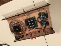
I recently finished a test build of a simple LM1875 chip amp. I used some cheap kits off ebay to build. I did this for a few reasons but primarily just to get my feet wet and I knew it would be an easy build with prefabbed boards. Also if I screwed something up, I'm only out a few bucks.
All that said, the amp went together and I was pleasantly surprise. It sounded good, like really good. I am by no means an "audiophile" compared to many on this forum but I was pleased.
I do have a few questions though. The schematic for the boards was included in the kit and it has a few more components than the recommended schematic in the data sheet for the 1875. As stated the amp sounded great, but it was a little bright to my taste and seemed to lack a little bass. I'm curious if that has anything to do with the component values and schematic of this board or if thats just due to cheaper components.
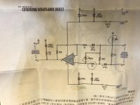
attached is a picture of the schematic (with the added components circled). Would live some input on if there are some components that don't need to be there, what values could/should change and maybe a general explanation of what happens to the tone when certain components are added/removed or their values changed.
I did buy some legit chips from digikey as well as the other components to build a point to point version of the amp as well. Just wanted to build a boarded one first.
Thanks!
Justin
apologies, for some reason the pictures are upside down. If thats a serious problem let me know and I'll re post them
I recently finished a test build of a simple LM1875 chip amp. I used some cheap kits off ebay to build. I did this for a few reasons but primarily just to get my feet wet and I knew it would be an easy build with prefabbed boards. Also if I screwed something up, I'm only out a few bucks.
All that said, the amp went together and I was pleasantly surprise. It sounded good, like really good. I am by no means an "audiophile" compared to many on this forum but I was pleased.
I do have a few questions though. The schematic for the boards was included in the kit and it has a few more components than the recommended schematic in the data sheet for the 1875. As stated the amp sounded great, but it was a little bright to my taste and seemed to lack a little bass. I'm curious if that has anything to do with the component values and schematic of this board or if thats just due to cheaper components.
attached is a picture of the schematic (with the added components circled). Would live some input on if there are some components that don't need to be there, what values could/should change and maybe a general explanation of what happens to the tone when certain components are added/removed or their values changed.
I did buy some legit chips from digikey as well as the other components to build a point to point version of the amp as well. Just wanted to build a boarded one first.
Thanks!
Justin
apologies, for some reason the pictures are upside down. If thats a serious problem let me know and I'll re post them
Attachments
Last edited:
330pFd and 1K is a 500KHz high-cut. NO effect in the audio band. I would not mess with them. It may solve real-world problems (taxi radio, cellfone stutter) that did not arise in the chip maker's lab.
The 1K NFB resistor and 47uFd cap make a 3.5Hz low-cut. -1dB @ 7Hz, -0.5dB @ 14Hz.... FAR flatter than any speaker.
The 22K input resistor and 10uFd cap make a 0.75Hz low-cut. No effect on audio response.
The 1K NFB resistor and 47uFd cap make a 3.5Hz low-cut. -1dB @ 7Hz, -0.5dB @ 14Hz.... FAR flatter than any speaker.
The 22K input resistor and 10uFd cap make a 0.75Hz low-cut. No effect on audio response.
Thanks for the input. so nothing in the circuit appears to be causing poor bass? likely due to a cheap clone chip then?
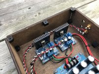
I did actually change the heat sinks before i ran it. This is what i have now, still too small? Could over heating cause the sound to thin out?
Also I changed to regular 22 gauge wire that i twisted. Does that have any affect on sound?
I know this is a cheap amp and i am just building it to get my feet wet but I would like to know if there is anything clearly wrong that i did.
Thanks!
Justin
Attachments
Use thermal paste on the back of each chip where it contacts heat sink
the heat sinks were adhesive backed so I assumed they use a thermally conductive adhesive. Do they appear large enough for the chip? I grabbed them from a tote at work from an EE so I could probably find data on them if that would help as they were in a package.
here are some better pictures after I took it apart, stained and sealed the case.
An externally hosted image should be here but it was not working when we last tested it.
An externally hosted image should be here but it was not working when we last tested it.
An externally hosted image should be here but it was not working when we last tested it.
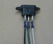
the power plug I am using has a fuse built in so the AC live goes through the fuse, then the switch then the brown wire on the transformer (110). the AC nuetral goes straight the the blue wire on the transformer (0). I don't have a ground hooked up because the transformer doesn't have one in the primary. would the earth ground go to the 0 volts on the secondary? (15-0-15)
The 10R resistor is a hum breaking resistor, it's function is described here on page 4 http://www.updatemydynaco.com/documents/GroundingProblemsRev1p4.pdfThe 10R to GND looks suspicious. A better approach is remove the 10R and route that path directly to the power supply GND. It won't look pretty but is the right way.
What speakers
JUSS10
It could be helpful to post as much information as possible about the speakers
that you connected to your amp.
Impedance, etc
Also, if you haven't done this, I would suggest verifying the voltages
coming into and going out of the power supply board. With a digital
multi-meter.
Voltages are probably ok, but it's a good idea to verify basics.
Speakers are BIC Venturi V62 models. 8ohms. cheaper speaker but always thought they sounded great.
Voltages going in are around 15V ac, around 18v coming out of the power supply board.
Voltages
I think I understand how you measured, but just to make sure I do - are these
statements all true ?
Voltage in at the power supply board is about +30 volts AC measured
from red to red?
Voltage out measured with positive lead on red, negative lead on green
is about +18 volts DC.
Voltage out measured with positive lead on black, negative lead on green
is about -18 volts DC.
Voltage out measured with positive lead on red, negative lead on black
is about +36 volts DC.
all true!
Voltages
Thank you for the quick reply.
With +/- 15 volts IN I would think that the volts out would be closer to
+/- 20 or 21 volts DC than to +/- 18
If your out voltage is lower than it should be, I don't see the reason for
it in the pictures.
I can hook up something here with +/- 15 volts IN to see what I measure.
However, note that the schematic that you posted does call for +/- 25 volts
DC. That would probably require a +/- 18 volts transformer.
Not a huge difference but it could make some difference in the power available for bass.
You now have a total of 36 volts compared to a total of 50 volts per the schematic.
Voltage test
With my test rig setup, with +/- 15 volts IN, I measure +/- 20 volts DC out.
I personally haven't had this situation - where the voltages are
about 10% less than expected. 18 vs 20
Maybe leaky diodes in the bridge ?
You could recheck connections and parts values on the power supply board.
Another test that could be done is to test the OUT voltages under load - that
is with your speakers connected and playing music or a test tone.
- Status
- This old topic is closed. If you want to reopen this topic, contact a moderator using the "Report Post" button.
- Home
- Amplifiers
- Chip Amps
- cheap LM1875 amp kit. Works great, few questions on tone