Basically, this is the datasheet's both-op-amps-paralleled circuit, converted into a double-sidede PC board layout. Red layer's the top, green's the bottom. The design's right off the datasheet and parallels both amps in a single LM4780 to produce higher output power without the tremendous increase in dissipation common in bridged designs. The tradeoff is the need for precision resistors in the voltage gain control, so that both amps' outputs are within a percent or less of each other.
Since it's easy to miss a little detail, I'll put this to additional eyes... Anyone see any obvious problems I need to address?
oO
Since it's easy to miss a little detail, I'll put this to additional eyes... Anyone see any obvious problems I need to address?
oO
Attachments
please note that the trace resistance must be kept within 0.1 milliOhm (0.0001 ohms) if you want to have the 0.1% matching listed on national... yep. 0.1 milliOhms isn't too much.
also, any traces that solder to the top of the board will be hard to solder onto the top of the board on pins under the IC.
that board is impressively sized (small) it looks like. depending on C4 and whatever terminal block you have, they may overlap, if no terminal block is used this is OK.
i'd have to say i'm most worried about the output traces. pretty small in a situation where every 0.1mOhm matters. and they are also pretty small and they will be higher current traces.
The IC looks pretty far from the edge, is this correct?
Cin should probably be longer, to accomadate a metalized-poly cap.
c11 and c12 are going to be larger value caps, they seem a bit small or closely spaced.
theChris:
Yeah, I saw that tenth-miliohm matching requirment and thought "yeah right, like hobbyists are gonna have gear capable of resolving that small a difference." I'm not going to even waste time trying to reach that kind of precise with the equipment at my disposal (although I do have a calibrated Fluke DMM that I think can read that low).")
As for the top and bottom soldering issue, the editor's ExpressPCB and I'm planning to have them produce a few of the boards. They'll pre professionally-made and all holes will be plated through, so that's not an issue. They'll even take care of all the vias in the groundplanes.
C4 shouldn't be an issue as my intention for the interconnects is to solder wires directly. I've had problems with contact corrosion in connectors before (I live across the street from a large saltwater bay) so for me it's better to solder everything and risk having to clip a wire later.
The backplate of the IC will be right at level with the edge of the board. I can trim the edge lightly if it misses by a few mils.
Already debating widening the mounting path for Cin, as you mentioned. I can move Rin over a little if need be to allow the cap to have some landing area on the board. Personally I'd rather leave caps out of the signal path but if ya gotta have it, well...
Also thought about the Ci pair. 47uF @ 50VDC in Tantalum is plenty small enough to fit, but I'm not sure tants are suited to amplifier DC coupling. I'll hafta do some research on that. If worse comes to worse I can float the caps off the board and lean them over the Ri pair.
As you've noted, the board's design goal is smallest size possible with proper design and groundplane layout to keep coupling and oscillation and so forth in check. To make the traces that carry current wider may run me into problems with coupling since I'll have to ditch some shielding (especially the B amp's output around Rf2 and Rsn2), so I debated making the traces thicker in the vertical plane instead by soldering some wire along the traces. I've used that trick before with supercompact power supplies and it works nicely, esp. if one uses solid bus wire and preshapes it properly before soldering it down.
I have some 24-ga. copper sheet too - I could make SERIOUS current capacity traces if I wanna go crazy.
Tensop:
Of course it's complicated - it's crawling with groundplanes.
But, since I'm going to have a replicator make 'em right off the drawing I can make it complex. (No way in hades I'd want to cook these up by hand - I don't have -that- much time. )
)
oO
Yeah, I saw that tenth-miliohm matching requirment and thought "yeah right, like hobbyists are gonna have gear capable of resolving that small a difference." I'm not going to even waste time trying to reach that kind of precise with the equipment at my disposal (although I do have a calibrated Fluke DMM that I think can read that low).
As for the top and bottom soldering issue, the editor's ExpressPCB and I'm planning to have them produce a few of the boards. They'll pre professionally-made and all holes will be plated through, so that's not an issue. They'll even take care of all the vias in the groundplanes.
C4 shouldn't be an issue as my intention for the interconnects is to solder wires directly. I've had problems with contact corrosion in connectors before (I live across the street from a large saltwater bay) so for me it's better to solder everything and risk having to clip a wire later.
The backplate of the IC will be right at level with the edge of the board. I can trim the edge lightly if it misses by a few mils.
Already debating widening the mounting path for Cin, as you mentioned. I can move Rin over a little if need be to allow the cap to have some landing area on the board. Personally I'd rather leave caps out of the signal path but if ya gotta have it, well...
Also thought about the Ci pair. 47uF @ 50VDC in Tantalum is plenty small enough to fit, but I'm not sure tants are suited to amplifier DC coupling. I'll hafta do some research on that. If worse comes to worse I can float the caps off the board and lean them over the Ri pair.
As you've noted, the board's design goal is smallest size possible with proper design and groundplane layout to keep coupling and oscillation and so forth in check. To make the traces that carry current wider may run me into problems with coupling since I'll have to ditch some shielding (especially the B amp's output around Rf2 and Rsn2), so I debated making the traces thicker in the vertical plane instead by soldering some wire along the traces. I've used that trick before with supercompact power supplies and it works nicely, esp. if one uses solid bus wire and preshapes it properly before soldering it down.
I have some 24-ga. copper sheet too - I could make SERIOUS current capacity traces if I wanna go crazy.
Tensop:
Of course it's complicated - it's crawling with groundplanes.
But, since I'm going to have a replicator make 'em right off the drawing I can make it complex. (No way in hades I'd want to cook these up by hand - I don't have -that- much time.
)oO
not sure if you saw my milled PCBs that i plan to sell. mine has no explicit mouning holes for the 0.1ohm resistors as i can't see it ever working to a point that i could _garuntee_. in anycase it's set up to allow many options. parallel is possible, but still, i can't see anywat to get the matching to 0.1% without extreme measures.
your's is also smaller. i got around the Cin issue by mounting the capacitors in a staggard fasion and assuming 5mm leadspacing, though they could be made larger, such will not fit perfect.
in an ironic update, i just realized that my planned components didn't fit. so i had to change that. in an ironic turn of events, i now have space for bigger caps on the board...
also,i don't like the idea of tantalum input caps. especially in a split supply board.
Hehehe, I redesigned my layout as well. It will stack slightly easier (two complete paralleled pairs in a 3.8 x 2.5" board) and the traces that will carry appreciable current are quite a bit wider. As an added plus I got room for a larger input capacitor and more clearance for the two Ci caps. And to sweeten the pot I got a lot better groundplane layout out of the deal.
Now, as for this whole match to within 0.1% stuff, I did some digging and since nobody bothers trying to get that close a match for multiple paralleled amps I'm not going to either. As long as they're within a close enough range that one isn't feeding back into the other (and the Rout resistors are there to help balance things) there shouldn't be any real-world issues.
Hey theChris, who's milling your boards? I would like to find a board maker that can mill 'em in small qty.
oO
Attachments
Aaaand, here are the boards, fresh from ExpressPCB. I panellized six of them to get their $59 prototyping price, which for my purposes is more than adequate.
Each board is 1.875" by 2.5", and will parallel both op-amps in a single 4780. If built with 0.1% resistors for the gain and feedback control and 1% or better resistors for output balancing, it SHOULD be possible to parallel several of these boards together - without any design or parts changes - to drive signals into almost-dead-short impedances without releasing the magic smoke.
But alas, I won't know that until I get the parts in from Mouser and build up a couple.
This is about as compact a board as is practical while leaving enoug space for components AND allowing for sufficient groundplane action to reduce loops and noise.
My gameplan is to build little amp "modules" with their own heatsink/fans (tunnel HSFs for Intel's Xeon processors - which are meant for 100-watt thermal loads!) and everything in one nice neat package. Need more power or a lower operating impedance? Add a module or two!
More on the design as I test 'em...
oO
An externally hosted image should be here but it was not working when we last tested it.
Each board is 1.875" by 2.5", and will parallel both op-amps in a single 4780. If built with 0.1% resistors for the gain and feedback control and 1% or better resistors for output balancing, it SHOULD be possible to parallel several of these boards together - without any design or parts changes - to drive signals into almost-dead-short impedances without releasing the magic smoke.
But alas, I won't know that until I get the parts in from Mouser and build up a couple.
This is about as compact a board as is practical while leaving enoug space for components AND allowing for sufficient groundplane action to reduce loops and noise.
My gameplan is to build little amp "modules" with their own heatsink/fans (tunnel HSFs for Intel's Xeon processors - which are meant for 100-watt thermal loads!) and everything in one nice neat package. Need more power or a lower operating impedance? Add a module or two!
More on the design as I test 'em...
oO
Update...
Parts to build two are on order from Mouser. When I get a pair built and tested I'll post my thoughts on them.
I am seriously considering a production run of the boards if the basic design holds up. Already have an idea on how to make 'em easily connectable in parallel, which could prove useful.
oO
Parts to build two are on order from Mouser. When I get a pair built and tested I'll post my thoughts on them.
I am seriously considering a production run of the boards if the basic design holds up. Already have an idea on how to make 'em easily connectable in parallel, which could prove useful.
oO
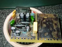
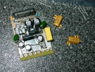
Next pic on the hit parade... Testing the fit and finish of parts on the board.
Near as I can tell I do need to change pin spacing and orientation on a couple parts, but otherwise the circuit fits rather well. The only negative is that to get the board this compact requires that some parts "float" - a few are not pressed flush against the board. From a purely electronic standpoint this does increase the chances of radiating or picking up interference, but I'll be ecstatic if the damn thing simply works.
The electrolytics are low-ESR and gain resistors are 0.1% 50PPM precision jobs that cost way too much for a 1/4-watt resistor.
Tomorrow I will probably have the board soldered up and be resy to start testing.
oO
Attachments
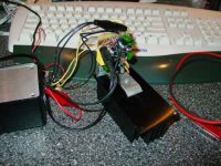
The two built-up boards survived my preflight testing - powering up with two 12VDC 1A switching supplies. Low enough voltage/current that problems won't be catastrophic, while allowing for obvious go/no-go testing, but sound quality's atrocious.
That part of the process completed safely, the first board got hooked into the eventual home of whatever amp I decide to stick with - a portable package with a welded square-steel chassis frame and an integrated LED power meter. Its power supply is currently only sporting 6,800uF of filter capacitance on the supply outputs, but there's plenty of room for me to add a few extra tenths of a Farad once everything else is to my liking. This same rig was going to hold a pair of TDA7293s, but they ended up being nothing but problems - thus far I'm not impressed with how much the 7293s like to explode violently over being looked at funny.
My initial impression is that in the same testbed system with LESS supply capacitance, the LM4780 in paralleled mode sounded BETTER than the TDA7293 single-mode that it will probably now be replacing. Less noise (a LOT less noise - the S/N ratio seems way better), no transients on power up/down, smooth operation to the ear when fed a sweeping sinewave, no apparent audible hum in the circuit despite my not using a true star ground. (My board design uses a lot of groundplane area on both sides of the board and a TON of vias to interconnect them for ensuring less resistance mismatch from GND terminals to the 4780's ground pins. Apparently this gameplan works!)
I'm using a higher-than-ideal supply voltage - 43VDC above and below ground at the board's power points - but aside from the expected extra heat the 4780 had no problem dealing with the slight overvoltage. (They want 84VDC max. ideally from V+ to V-.) The heatsink I used for the initial full-supply test was only 4.5" x 2.5" x 1.25" but took an hour at about a watt's output continuously to get warm enough to be of any interest. (Insulator is a single layer of Kapton MT100 film, with standard aluminum-oxide white thermal goo as the interface layer.) Heatsink is back to room temp in three minutes. I suspect that using a Xeon heatsink and fan (as in the Xeon processor) will be adequate for everything short of sustained operation at or very close to the 120-watt limit of each paralleled-4780 board.
So far I'm impressed. I just hope they keep working for more than a few hours...
oO
I'm interested in the outcome of your experiment too.
Not just the sound quality, but the survivability of the
chip at those voltages. You may be pushing the SOA
limits into a given speaker load, some of which will be
a lot more demanding than others. Hopefully the
protection circuit will save them from terminal abuse.
I'm listening to my first attempt based on LM3886s,
driving Acoustic Research AR-11s (4 ohm) via Kimber
4TC cables, arguably a demanding load for chip amps.
So far, so good, but I'm running at a lower voltage
and not pushing the volume too hard. One channel
has active voltage regulation with LM317/LM337 devices;
I don't recommend this practice.
I also incorporated the suggested load protection
RL circuit and have a fairly generous heatsink. It's
all point-to-point 'haystack' wiring.
I'm more interested in the LM4780s for the 'serious'
amplifier as it should be a good bit more rugged. I
may use BrianGT's newest board and better quality
parts, though with a lower voltage toroid in the
power supply than the one I'm using now.
So far I'm reasonably pleased with the sound quality;
not quite the equal of my Leach amp, but quite
good even with a strong bass bottom. There's a
good soundfield and good imaging, and I hope the
LM4780 will equal or better it.
I'm leaning towards a compact 'integrated' amplifier
with three line level inputs from my tuner, CD and
computer sound card. Got most of the parts, but
I'm stumped on how to build a decent looking chassis
for it.
Damon Hill:
Well, according to the datasheet the absolute supply limit is 94 volts and I'm feeding 86, but also according to the datasheet the overvoltage protection could kick in at anything above 84, so once I get some beefier heatsinking in place I'll hook up my homebuilt 130W RMS speakers (4 ohm impedance, which WILL stress the amps) and see if it can sustain a sine sweep at say 75 watts.
One thing I did notice is that there's NO DC on the outputs AT ALL. My calibrated Fluke DMM was reading 0.0007 VDC (yes, it's a 4-1/2 digit scale) across the outputs during one of my no-input-signal checks. This is definitely a good thing - tells me I didn't build a pooch-screw right into the circuit.
As for how to house your completed project, I've seen some incredibly sharp buildups here. Plenty of ideas around this board to imitate or be inspired by.
oO
- Status
- This old topic is closed. If you want to reopen this topic, contact a moderator using the "Report Post" button.
- Home
- Amplifiers
- Chip Amps
- Paralleled LM4780TA PC board design - How's this look?