Hi guys
Today I used the supplied diagram to wire the twin secondaries of my transformer. I measured the AC voltage on the secondaries and got a perfect 25-0-25.
That part's fine. But once I wired the secondaries to the rectifier and turned the power on, I got a terrible mechanical "rrrrrrr" sound and the transformer and rectifier started to get VERY hot in just a few seconds. I'm thinking something must have shorted so I quickly shut it off.
What in the world could I be doing wrong? I even have 2 rectifiers and tried it with both but as long as I connect the marked AC pin to ANY other pin on the rectifier, I get that horrible sound!
The problem is that on my rectifier, only one AC pin and one + pin is marked. The other 2 are not. I assume that the corresponding AC pin is diagonally across from the marked AC pin, and same for the + pin right? Even so, I did try wiring the AC pin to every other pin, but no matter what, that sound/heat persists. The transformer works fine when its not connected to the recitifer and I measure the voltages off the secondaries.
Since then, i managed to get the pin diagram for the recitifer just to make sure i got things right and i did. So i just cant understand whats happening
I dare not go any further until I am able to solve this problem and I hate to ask simple questions like this but i've looked pretty much everywhere and no one has mentioned a similar problem. I even scoured the whole decibel dungeon site and couldn’t find anything that could help my problem.
Hope to get some help, thanks so much
P.S the recitifier is a generic 100V 25A bridge from www.partsexpress.com
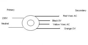
Ok i've drawn a rough sketch(attached)
originally, i connected black to yellow(0V) with red and orange going to the AC terminals of the recitifer. Done this way, i get 25V from either of the secondaries to the 0V secondary and 50V from one AC secondary to the other AC secondary. When i connect this to the rectifier, i get that terrible sound and heat
Then i followed your advice and tried to swap one of the secondaries. So now the red and black wire is switched, i.e. red and yellow are joined together(0V) and black and orange are the AC leads going to the rectifier. Done this way, i get 25V from either secondary to 0V but when i measure voltage across the AC terminals, i get a very mysterious 0V AC on my multimeter. When i hook up the rectifier everything seems ok, but i get no DC voltage off the rectifier DC output terminals.
Doesnt seem to be working at all. I'm very disheartened any idea what i'm doing wrong?
Kevin
originally, i connected black to yellow(0V) with red and orange going to the AC terminals of the recitifer. Done this way, i get 25V from either of the secondaries to the 0V secondary and 50V from one AC secondary to the other AC secondary. When i connect this to the rectifier, i get that terrible sound and heat
Then i followed your advice and tried to swap one of the secondaries. So now the red and black wire is switched, i.e. red and yellow are joined together(0V) and black and orange are the AC leads going to the rectifier. Done this way, i get 25V from either secondary to 0V but when i measure voltage across the AC terminals, i get a very mysterious 0V AC on my multimeter. When i hook up the rectifier everything seems ok, but i get no DC voltage off the rectifier DC output terminals.
Doesnt seem to be working at all. I'm very disheartened
any idea what i'm doing wrong?Kevin
Attachments
ok then, to avoid confusion and to prevent anybody from getting killed, the rectifier bridges should be hooked up like this:
I've used the standard (EU?) toroid color coding scheme. If you're not sure, just check the resistance. red-yellow should have some resistance, the other pair too. infinite resistance means you've got the wrong wire (not the same secondary winding)
this should do it...
/matti
An externally hosted image should be here but it was not working when we last tested it.
I've used the standard (EU?) toroid color coding scheme. If you're not sure, just check the resistance. red-yellow should have some resistance, the other pair too. infinite resistance means you've got the wrong wire (not the same secondary winding)
this should do it...
/matti
Oh dear,
You mean i need to use both my rectifiers(i originally bought the second as a spare). The colour coding is a little different to the one on my transformer though, how do i interpret it? Is there a way for me to just use one? My transformer has twin 25V secondaries. I'm aiming to get 25V AC to 36V ac for the rails of the amp(my gc will be the LM3875 version)
BTW i hope my nick doesnt offend. I got an email once from a guy who asked me to change it but i think people misunderstand, its actually a tongue-in-cheek kinda name, not meant to offend or anything. Maybe thats why hardly anyone helped me in my earlier threads
Just to update:
I have tested the leads as mentioned in the above post for resistance. I have found the matching secondaries and tried wiring them to the rectifier AC terminals again as explained in the diagram above. It made that sound/heat again!!! What in the world...??
don't forget to use a fuse in front of the toroid, that might make it a little safer...
i can't reccomment using only one bridge, i've tested it and somehow it degrades the sound. makes it sound very dull.
what are the rectifier's specs? are you shure you haven't blown them up in previous attempts to get a working bridge ?
25v secondaries will, after rectification provide you with ~35V DC.
(ans yes, i think your nick might be the reason for not getting too much help on these fora)
hello everyone,
Is there a way to check with a multimeter if the rectifier is spoilt? I have subjected the bridges to that buzzing/heat many times but never more than a few split seconds at a time. I never saw any smoke or heard any explosions thus far(basically from the exterior, nothing seems to be burnt)
The rectifier i am using is this one:
http://www.partsexpress.com/pe/showdetl.cfm?&DID=7&Partnumber=050-060
I have 2 of them at this point.
Just to recap, i tried to wire it the way matjans described in his post diagram but the buzz/heat persists.
Really appreciate any help!
yes there is. a diode should have a low resistance one way (red probe on anode or + and black probe on cathode or -) and a very high resistance the other way around.
these are REALLY basic electronics questions. Before building an amplifier, or in general trying anything having to do with high voltage may i humbly suggest either reading up on your electronics knowledge or better, try something *NOT* having to do with high voltage?
It might save your life... or your house, if the whole thing decides to go up in flames. One very nice project to get you started with is this headphone amplifier . It's basically a gainclone. A very simple headphone amplifier run off a battery. Better still, this headamp makes a perfect preamp (i'm using one as we speak/type).
This will get you started on the basics of electronics / opamps. Not that i'm such an EE god but i do know my basics and i must say this makes it a lot safer. Good luck.
Well,
Notwithstanding the fantastic help i have been getting from everyone in this thread so far(for which i must say at the onset, i am eternally grateful for), i feel i need to rant a little.
Its not the first time someone has told me to 'try something easier'. Forgive me for saying this but i thought that this forum was about helping people with an interest to learn things they want to? I admit, i have no formal education in EE besides high school physics which i took a decade ago but that doesnt mean that just because i'm not an EE means i have to keep trying something easier do i?
I spent months researching on what DIY project to go for and when i finally came across the decibel dungeoun website i read what the guy said, looked at the schematic, played it out in my mind and thought to myself, hey, i think i can do this. The fact that the site said no EE background required was a big thing for me and i trusted it. So i gave it a shot and read as much as i could and tried to teach myself as much as i can, using this forum as a last resort only so i dont bother the experts here.
I'm not very rich, and after taking the big leap and ploking down about 150USD worth on electronics for a 4 channel gainclone(with the transformer eating a large portion of the cost) it just makes me feel awful when i get told to 'forget it and try something else'. It seems like such a waste to throw this stuff i spent so long saving up for away and not using it.
I mean, i've already committed myself and i really want to finish it. I know i've got this licked, and i sincerely believe i can actually build this thing once i find out what in the world is wrong with my PS wiring.
I've followed every piece of advice in this thread but the problem persists. its not that i havent tried the tips, but nothing seems to be working. I guess what i'm really trying to say is that i know i dont know very much, but is it too much to ask for a little help?
/end rant
I'm sorry if i offended anyone, i really do. Its just that sometimes i think this forum has an "Experts only, beginners not welcome" sign hanging on the door and somewhere along the line i forgot to read it before i came in
rereading my post i may have sounded a little harsh. But then again, playnig around with 230V can be pretty dangerous. Just make sure you don't get killed and we'll all be happy.
to prevent you from getting killed i *REALLY* think you should use a fuse. get one (with a holder), place it in line with one of the primary windings. use a 2-3 amp slow blow fuse. And get a handful of fuses. DONT DO ANYTHING WITHOUT A FUSE !!
OK, back to the rectifiers. Have you tested them yet ?
if not:
put the multimeter in resistance-measruring mode.
to test the diodes in a rectifier bridge put the red probe on the lug with the AC marking, the black one on the + marking. the mm should give you a resistance of a few ohms (depending on type of rectifier). switch probes (ac black, + red) and it should gice you an infinite resistance (or unmeasurable anyways).
now, turn the rectifier a quarter to the right. repeat the process. and again, and again. each side of the rectifier should only have a "one-way" resistance, the other way around, it should be infinite.
If this is true, your bridge is OK, if it isn't get a new bridge.
to L S ( S S)
I think some people are forgetting the values when dealing with the 3875.........
Interesting. the basic power supply for any gc needs a ct that serves as the 0 volts. however you configured the transformer so that 50 volts goes to the rectifier, meaning that after the rectifier you will get approx 50 volts multiplied by 1.4 (grosso modo) and then the result will be more than 70 volts DC (EE's please correct me if I am wrong) a little bit too high if you ask me.
most guys here use a 18, 22,24 or 25 volts CT (centertapped) tranformer and so after rectification this # goes up to 38 volts or so, pretty high for it's purpose in this case.
I do not posess the knowledge to help you (although I would like to) , mainly because I am completely incapable on the electronics field, however I would tackle your problem by using another transformer, one that has 3 or 6 wires.
3 wires representing x volts, 0 volts or CT, x volts , with x = # of volts.
6 wires would be good for 2 gc's
the measurement of the 3 wire trannie should preferable not exceed 25 volts or 13 volts between one lead and the CT.
I have a similar toroid like you and it is laying here waiting for another project, not for a gc system.
Jean-Pierre
as I said before, I have no knowledge in EE whatsoever so please consult a capable person before proceeding.
I think some people are forgetting the values when dealing with the 3875.........
lovely slut said:i connected black to yellow(0V) with red and orange going to the AC terminals of the recitifer. Done this way, i get 25V from either of the secondaries to the 0V secondary and 50V from one AC secondary to the other AC secondary. When i connect this to the rectifier, i get that terrible sound and heat
Interesting. the basic power supply for any gc needs a ct that serves as the 0 volts. however you configured the transformer so that 50 volts goes to the rectifier, meaning that after the rectifier you will get approx 50 volts multiplied by 1.4 (grosso modo) and then the result will be more than 70 volts DC (EE's please correct me if I am wrong) a little bit too high if you ask me.
most guys here use a 18, 22,24 or 25 volts CT (centertapped) tranformer and so after rectification this # goes up to 38 volts or so, pretty high for it's purpose in this case.
I do not posess the knowledge to help you (although I would like to) , mainly because I am completely incapable on the electronics field, however I would tackle your problem by using another transformer, one that has 3 or 6 wires.
3 wires representing x volts, 0 volts or CT, x volts , with x = # of volts.
6 wires would be good for 2 gc's
the measurement of the 3 wire trannie should preferable not exceed 25 volts or 13 volts between one lead and the CT.
I have a similar toroid like you and it is laying here waiting for another project, not for a gc system.
Jean-Pierre
as I said before, I have no knowledge in EE whatsoever so please consult a capable person before proceeding.
mat,
dont worry its ok, i really dont mind. i guess its all part of the learning process. for what its worth, your help was really..well...helpful, lol
OK based on your advice i have tested the leads of the rectifiers
The results dont seem to make sense!
I have tried the combinations you requested, and i dont get one way results. Basically it works like this, one way i will get very high(but measurable) resistance as i move across the terminals until i come to the second last set before i come full circle(where there will be an unmeasurable, i assume infinite, resistance). It works the other way round as well when i fip the probes
So basically 2 adjacent pairs will have high resistance and the other 2 pairs will have high resistance when i flip the probes. Other that those cases, i will get no reading.
All terminals on the rectifier have connectivity.
The result is also consistent with both recitifiers.
I'm not sure what to make of it. I hope this doesnt confuse you half as much as it confused me!
uvodee> After reading your post, it kind of makes sense. Unfortunately, i have no idea if you are right idea. I got the idea to wire up my transformer as given in my earlier diagram(which is causing the short) from another member here i emailed. How he told me to wire it was pretty consistent with the manual of the transformer which i read as well. I was actually planning on measuring the DC voltage off the recitifier to test before i actually finished the circuit just to make sure though. Unfortunately, i cant complete the PS so i am still unsure which method to use!
Lovely Slut,
There is a section on wiring up a transformer for a gainclone on this page: http://www.decdun.fsnet.co.uk/gaincloneFAQ.html
Re: your name; we are all a bit odd to be doing this hobby aren't we?
There is a section on wiring up a transformer for a gainclone on this page: http://www.decdun.fsnet.co.uk/gaincloneFAQ.html
Re: your name; we are all a bit odd to be doing this hobby aren't we?
Ah thats right, thats the motivation for me wiring it the way i did as in the first post when this problem started(in the learning process, i read the entire website back to front many many times so i wouldnt need to ask any questions here except the ones i really couldnt get answers to). Correct me if i am wrong, but doing it that way means i only need one bridge rectifier correct?
I believe mat's method is equally viable and makes use of 2 bridges instead of one. Looking at the diagram intuitively, both methods appear to be the same(with the exception that mat's uses 2 bridged)
I have tried to wire the rectifier up both ways and in both cases, i get that horrid buzz & heat( i presume shorting).
And yes, you're right, i am wierd lol
The difference between the two circuit diagrams is probably that one shows just one channel and the other shows both channels. Very often diagrams just show one channel and you have to repeat it to get stereo; the cause of much of my early confusion I presume you are building a two channel (stereo) gainclone. You have options as regards the transformers (tx) and bridges:
a) 1 transformer to 1 bridge, split to both chips: [tx]--------- [bridge]-----[terminalblock]========== to chips
b) 1 transformer split to 2 bridges, to both chips: [tx]--------[terminalblock]=======[2 bridges]====== to chips
c) 2 transformers to 2 bridges to both chips: [2 tx]=======[2 bridges]====== to chips
(by split, I mean feed the single wires into one side of a 5W rated (or higher) terminal block and then connect two to the other side)
Two bridges are nearly always recommended (as you know) and the difference between 1 and 2 transformers is a warmer but softer sound with 1 and a fuller but slightly harsher sound with 2. Basically it is down to what you prefer; I like option b best.
Please get yourself a new pair of bridges - I know it's a pain, but from what you say it does sound as if you have burnt yours out. Are you sure your bridges are rated high enough, ie: can they accept atleast 25VAC (50 to be safe) and around 15W?
I presume you are building a two channel (stereo) gainclone. You have options as regards the transformers (tx) and bridges:a) 1 transformer to 1 bridge, split to both chips: [tx]--------- [bridge]-----[terminalblock]========== to chips
b) 1 transformer split to 2 bridges, to both chips: [tx]--------[terminalblock]=======[2 bridges]====== to chips
c) 2 transformers to 2 bridges to both chips: [2 tx]=======[2 bridges]====== to chips
(by split, I mean feed the single wires into one side of a 5W rated (or higher) terminal block and then connect two to the other side)
Two bridges are nearly always recommended (as you know) and the difference between 1 and 2 transformers is a warmer but softer sound with 1 and a fuller but slightly harsher sound with 2. Basically it is down to what you prefer; I like option b best.
Please get yourself a new pair of bridges - I know it's a pain, but from what you say it does sound as if you have burnt yours out. Are you sure your bridges are rated high enough, ie: can they accept atleast 25VAC (50 to be safe) and around 15W?
Possibly a shorted turn
Toroid right? You might be experiencing "shorted turn" phenomina. In other words, your circuit might be perfectly fine but your transformer bolt could be conducting. This results in high temperature and a very very loud buzzing noise with mechanical vibration. Try it without any bolts on the xformer, if it is still screwy with nothing through the toroid it can't be this. It happened to me, but only when I deflected the lid on my chassis to complete a circuit to the xfrmer bolt. For more info see this thread.
http://www.diyaudio.com/forums/showthread.php?s=&threadid=30676
- Status
- This old topic is closed. If you want to reopen this topic, contact a moderator using the "Report Post" button.
- Home
- Amplifiers
- Chip Amps
- GC Power Supply Trouble