Thanks for the tips. At this point the transformer(yup, a toriod) hasnt been bolted down. its just sitting on my ironing board(sic!) for testing before i actually assemble. The sound appears to be coming from the rectifier(maybe the transformer as well i'm not sure) but both the rectifier and trans get very hot in a few split seconds. I havent used the bolt yet at this point.
the transformer works fine with proper voltage measurements meeting spec when the recitfier is not connected.
I will difinitely be trying to get some new recitfiers to try again(sigh)
What i fear is if the problem persists with the new bridges, then, i will really be stuck wont i....
Here's the rectifier i plan on getting: does it look ok?
http://www1.jaycar.com.au/productVi...d2=&pageNumber=&priceMin=&priceMax=&SUBCATID=
I will be running 36V approximately for the rails and it will be a 4 channel gainclone(planning on building linkwitz orions one day and a 4 channel would be great for running the mid/tweet active) and the whole amp will be powered off my 300VA toroid. The rectifier seems to exceed spec by quite a large margin but since recitifers arent that expensive i though "what the hey..."
About the resistance readings:
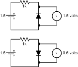
A diode needs around 0.6 volts to conduct any significant current.
It's quite common that a regular DVM doesn't put out enough voltage when measuring resistance, and thus the diodes won't conduct regardless of polarity. Some DVM:s have a dedicated diode test mode, which will measure voltage across the diode.
Without that, you can take a 1.5volt battery and a resistor (100-1000 ohms, doesn't really matter much). Connect those in series and in series with the diode. Measure the voltage across the diode. Should read 0.6 volts with the diode in conducting mode, and 1.5 volts in reverse mode. See attached drawing.
However, it seems your briddges aren't short circuited, so that doesn't explain the currents. It sounds like you've connected the transformer windings to the output pins of the bridge, rather than the input pins. That would result in large assymetric currents, which can easily get the transformer humming wildly.
To protect your gear, connect a 60W light bulb in series with the primary winding. Makes for excellent current limiting when testing.
Rune
Attachments
Circ
OK, sorry I couldn't help. Check your power supply circuit carefully and then let it rip with the new bridge (that one looks fine). You know when I made my first diy project about 15 years ago, I killed off about 10 diodes doing the same thing as you, for no apparent reason (exept there was no heat or noise). I solved the problem using a massive diode bridge like you have indicated on your post. Keep at it. If you are really stuck, post a picture of everything with measurements.
OK, sorry I couldn't help. Check your power supply circuit carefully and then let it rip with the new bridge (that one looks fine). You know when I made my first diy project about 15 years ago, I killed off about 10 diodes doing the same thing as you, for no apparent reason (exept there was no heat or noise). I solved the problem using a massive diode bridge like you have indicated on your post. Keep at it. If you are really stuck, post a picture of everything with measurements.
nervous reply!
I consider this not really rocket science but it is difficult enough for me to again reply, I am not a rocket scientist anyway.
Matjans was right but maybe i should translate it in Flemish advice.
your red ac needs to go to a rectifier , let's call the rect "lul".
your black wire 0v also needs to go t the same "lul", ofcourse the other ac entry!!!
your yellow ac goes to the second (yes you need 2 recs) rectifier, let's call this on "lol"
your orange 0v goes to the same rectifier "lol" but again ofcourse the other ac entry.
now after haveing done this
one new wire goes from LUL's dc neg to LOL's dc pos and from this connecting wire you will have a 0 volt out that you NEED to have AND use!!!!!!!!
now from LUL's DC pos there is one wire going to the board or wiring p2p as the positive (plus)
and from LOL's DC neg there is the other wire going to the board or p2p as the negative (minus)
so you end up with 3 wires, it is to say : a pos, a neg and a 0 volts
before you start connecting these wires to a p2p or board, please measure them, and post the result here.
J-P
Hello Blackreplica, it looks like to me you may have wired your bridge recifier incorrectly. I downloaded your schematic and revised it (I will post it here). You may want to wire your bridge rectifier as shown in the modifications to the schematic. Hopefully you didn't blow one of the diodes in the bridge.
Represented in the schematic, I drew in a 60 watt lamp (as posted by runebivrin), you want that in series while testing to limit damaging current in case things go wrong. If there is a short in the wiring or a mistake, the lamp will glow brightly, while protecting your transformer and bridge rectifier from damage.
(Please bear with my bad drawing of the lamp).")
Good luck Blackreplica, just wire the bridge rectifier as shown in the schematic (if it is alright, I highy doubt you damaged the transformer, as it would start smoking), things should be OK.
P.S.>Be careful around the mains voltage, I see yours is 230 volts. You don't want to get a hold of that!
Represented in the schematic, I drew in a 60 watt lamp (as posted by runebivrin), you want that in series while testing to limit damaging current in case things go wrong. If there is a short in the wiring or a mistake, the lamp will glow brightly, while protecting your transformer and bridge rectifier from damage.
(Please bear with my bad drawing of the lamp).
Good luck Blackreplica, just wire the bridge rectifier as shown in the schematic (if it is alright, I highy doubt you damaged the transformer, as it would start smoking), things should be OK.
P.S.>Be careful around the mains voltage, I see yours is 230 volts. You don't want to get a hold of that!
Attachments
Hello everyone,
This is great, and everything here is really helpful. I think the way to go is with the new bridge and start again(am planning on getting em tomorrow, unfortunately, decent electronics parts are really troublesome and expensive to get in australia)
Just to clarify, i have been suggested with 2 alternative methods of wiring up the PS with one bridge(as suggested by rimband(thanks so much for editing the diagram, it makes so much sense now, i think that was how i was wiring it from the start though) and another with 2 bridges(as kindly pointed out by mat and uvodee). Aside from sound quality implications, is there really a difference between using one bridge or 2? Specifically, Will it result in a different rail votage between the 2 methods? I ask this because i need to get 25VAC to the rectifiers. My trans is a twin secondary 25V transformer(i believe both secondaries are 25 volts). Between the single and double rectifier method, are they both situations where the secondaries are wired in parallel?(thats what i should be aiming for right, since if i wire in series i would be double the voltage to 50V instead?)
Just a curious piece of info, i know what a 230V shock feels like. No no, no accidents with the amp, its just that when i was 8 years old i think i had an unfortunate accident when i pulled out a plug from a wall socket with the switch still in and one of my fingers touched the pins on the plug while it was still coming out of the socket(lol, dont ask). I think i was electrocuted for about 10secs before i even realised what was happening to me. thats an experience i wont forget anytime soon!
Edit: Just in case i may have mis-specced the transformer i thought i'd post a link directly to the transformer i have right now
http://www.rsaustralia.com/cgi-bin/...D=auie&3258152795=3258152795&catoid=-83963296
its the 2×0-25V, 6·0A one.
I am aiming to get 25V AC output going to the rectifiers and not 50V. If there is a difference in the 2 abovementioned methods of wiring the secondaries(1 bridge vs 2 bridge method) do let me know! Thanks so much!
Also, I may be getting a little ahead of myself by asking this too but i was also wondering that when actually wiring up the amplifier, would i eventually connect power/signal ground from the amplifier circuit to the 0V point of the PS or would i just leave them floating(not sure if thats the right term)?
blackreplica said:
I am aiming to get 25V AC output going to the rectifiers and not 50V. If there is a difference in the 2 abovementioned methods of wiring the secondaries(1 bridge vs 2 bridge method) do let me know! Thanks so much!
Hi
u can construct a +/- VDC supply using a 2-sec windings and 1 rectifier.
Check out the AKSA website:
http://www.aksaonline.com/products/products_aksaasmbly.html
if u do so, u gotta short the black and yellow leads and tied them to ground.
most guys here use a 18, 22,24 or 25 volts CT (centertapped) tranformer and so after rectification this # goes up to 38 volts or so, pretty high for it's purpose in this case.
Hello Uvodee,
Since we have been discussing this before , I feel you won't be offended if I question this statement, and ask for another opinion.
PLEASE SOMEONE:
I thought that most people use transformers that have dual outputs, each pair is 18-25 volts.
1. Isn't this the equivalent to a 36-50 volt center tapped transformer?
2. So... if you use a center tapped trannie, don't you want a 36 to 50 volt center tapped, which has two 18 to 25 volt legs? and one common?
I think we're getting close to the reason you're having problems. You really don't want to parallel the secondaries, neither before nor after recitfication.
What voltage do you want after rectification and filtering?
With 2x25V AC, you'll wind up with ±35V, which is on the high side for a classic GainClone. There's no really good way to turn that into ±17.5V, which would be a bit on the low side anyway.
I'll leave the voltage issue for now, and focus on the wiring. Just wire one of the secondaries to the AC connections of a single bridge. Leave the other scondary unconnected. You should now measure somewhere between 25 and 35 volts across the DC terminals of the bridge, depending on how your multimeter reacts to unfiltered DC.
Rune
thank you
Thanks Runebivrin.
I could not have expressed myself better than with your message.
25 volts before and 38 volts after rectification and a 10 pct tolerance on capacitors comes close to the maximum 84 volts/2 = 42 volts per rail you can have using a LM 3875.........
it is as simple as that
J-P
if you feed the 3875 anything higher, you get a load roarring noise ... and other consequences
furthermore
I have, from personal experience, noticed that a lower voltage brings better sound . My preference goes out to 18 volts before rectifier and also not more than 5 amps which I agree will not give you 56 watts at the end but to me it sounds much much better. I hear warmer sound when using these trannies. I have a set up with 25 volts 8 amp and that is good enough for modern day music but leaves color and warmth behind of classical recordings....
my idea is supported by the fact that this chip is found in some hitachi and toshiba tv's and they list 2 - 20 watts as maximum rating and i believe that there is a valid reason for : do not overdo the supply.
J-P
J-P
would i eventually connect power/signal ground from the amplifier circuit to the 0V point of the PS or would i just leave them floating(not sure if thats the right term)? [/B]
The signal ground should be connected with a thin wire to the power ground, and the power ground should be connected with a thick wire to the 0V of the psu.
Hi all,
I actually went for the 25V transformer because it was my intention to give the amp 35V DV on the rails(it was recommended on decibel dungeon, i think i havent mentioned this before, but my GC will be using the LM3875TF chips of which many others in this forum have made before)
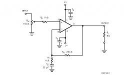
The schematic i will be using is the one found in the typical application diagram in the lm3875 datasheet(it looked to be the easiest to make, i believe it is inverted although i dont know what that means really, at this point!)
runebivrin,
I am trying to get 35V DC as you have mentioned for my GC. When you recommend i use just one set of secondaries, then where is the 0V lead going to come from? Wouldnt i need to use both secondaries to supply the negative and positive rail(and 0V reference) or do you want me to do one first just to make sure everything is working before i make the other rail?
I actually went for the 25V transformer because it was my intention to give the amp 35V DV on the rails(it was recommended on decibel dungeon, i think i havent mentioned this before, but my GC will be using the LM3875TF chips of which many others in this forum have made before)
The schematic i will be using is the one found in the typical application diagram in the lm3875 datasheet(it looked to be the easiest to make, i believe it is inverted although i dont know what that means really, at this point!)
runebivrin,
I am trying to get 35V DC as you have mentioned for my GC. When you recommend i use just one set of secondaries, then where is the 0V lead going to come from? Wouldnt i need to use both secondaries to supply the negative and positive rail(and 0V reference) or do you want me to do one first just to make sure everything is working before i make the other rail?
ropie,
Thanks a lot for the help on wiring the ground. That was exactly what i was looking to know. Thanks a lot!
uvodee,
Thats an interesting finding. its a shame i already bought my transformer so it might be a while before i actually try your way
I'm not after maximum power from this amp but i decided to make it this way because i noticed that transformer prices didnt vary much depending on their secondary voltage rating so i thought to get the most power for my dollar and went with the upper recommended voltage limit for the LM3875
Well, 2*25 VAC should work OK, but you will need a decent heat sink if you play loud.
Using two rectifier bridges (one per rail) might actually be better in the sense that it gets more diodes in series in the PSU, so you'll get a greater voltage drop.
As for testing diodes, I've on occasion used a LED in series with a 9V battery for that purpose. Anode of led to + of battery, and connect the diode under test between battery- and LED cathode.
LED should light in one direction and remain dark in the other.
You can of course use a small light bulb as well.
A bridge has 4 diodes in it, so that's a total of 8 tests to run to see if it's fully functional:
AC1 to - (both directions)
AC1 to + (both directions)
AC2 to - (both directions)
AC2 to + (both directions)
Rune
Power Supply Question
Here is a power supply question from a newbie GC cloneee. For my GC power supply I have come across output from 150VA upto 500VA, generally 25V X 2 as standard.
Question. Higher VA rating may be more noiser then the lower one?
Question. What would be the advantage of the higher VA ratings?
Question. What if any, are the factors in play regarding the Amperes in this (My torroid said 300VA, 2X25V,6A?
Regards and happy ears!
Time for an update!
I love you guys! I went and bought 2 new rectifier bridges earlier today and tried them out.
I would also love to add that the light bulb idea for safety purposes is a BLOODY good idea(if any other newbies like me come across this thread in a search, please heed this advice!) All it took was about 2 mins of soldering and i wired it to the primariy wire of the transformer and even when i tried the old bridges all i got a was a very bright bulb(no sound, no heat). I cant say enough what a great thing it was to have a safety device like that when testing the PS.
So anyway, i tried the new bridges out...lo and behold, everything worked! The bulb was not lighted and there was no sound and heat. tested the DC terminals of the bridge and got a reading! So i guess the old bridges were spoiled(wonder how it happened).
The method i tried was to wire each set of secondarys to one rectifier. Since things have worked out, i shall use a dual rectiufier setup for the amp.
I really would like to thank you guys so much for the help. Without all the helpful input i probably never would have solved the problem!
Just a curious observation however. The AC voltage measurement on the secondaries of the transformer is 25V AC. When i hooked up the rectifier to the secondaries i got a very strange 27.xxV DC. This is kinda strange isnt it? I mean, shouldnt i be expecting something like 25 x 1.414 = 35V DC after recitication based on the AC input voltage? Where did the other 8 volts go?
Tops> I am by no means an expert as this thread has probably proved many times over but i'll try to answer what i can
1) Higher VA rating may be more noiser then the lower one?
I'm not sure about this but my 300VA makes a very very very slight hum when its operating. It can only be heard when i puyt my ear about 5cm away from the transformer. If it was in a casing, theres no way you would be able to hear it. Its quieter than a whisper across a room
2)What would be the advantage of the higher VA ratings?
I believe every amp needs a minimum VA to operate reliably or safely. This depends on a lot of factors like the chip you use or the number of channels or the rail votage(not sure about this one?). As long as you have enough VA for your amp and all its channels, you should not have a problem. I believe some here tend to use higher than needed VA transformers. There may be an implication on the sound quality but i'm not sure about this either. Nevertherless, i think its a good rule to get as much VA as you can afford, for headroom in the amp's power supply and you can even re-use it in future for a more powerful amp if the fancy takes you
3) What if any, are the factors in play regarding the Amperes in this (My torroid said 300VA, 2X25V,6A?
I believe the formula for VA is something like this
VA = V x A
So if i have a 300VA transformer with 25 V secondaries(x2),
300 = 25(2) x A
A = 300/50
A=6
I think thats how the relationshop goes. So given a fixed secondary voltage, with a higher VA, the transformer can supply a larger current to the amplifier, which allows you to power more channels for example.
It's nice to help someone for a change I just hope i didnt make a mistake somewhere
I love you guys! I went and bought 2 new rectifier bridges earlier today and tried them out.
I would also love to add that the light bulb idea for safety purposes is a BLOODY good idea(if any other newbies like me come across this thread in a search, please heed this advice!) All it took was about 2 mins of soldering and i wired it to the primariy wire of the transformer and even when i tried the old bridges all i got a was a very bright bulb(no sound, no heat). I cant say enough what a great thing it was to have a safety device like that when testing the PS.
So anyway, i tried the new bridges out...lo and behold, everything worked! The bulb was not lighted and there was no sound and heat. tested the DC terminals of the bridge and got a reading! So i guess the old bridges were spoiled(wonder how it happened).
The method i tried was to wire each set of secondarys to one rectifier. Since things have worked out, i shall use a dual rectiufier setup for the amp.
I really would like to thank you guys so much for the help. Without all the helpful input i probably never would have solved the problem!
Just a curious observation however. The AC voltage measurement on the secondaries of the transformer is 25V AC. When i hooked up the rectifier to the secondaries i got a very strange 27.xxV DC. This is kinda strange isnt it? I mean, shouldnt i be expecting something like 25 x 1.414 = 35V DC after recitication based on the AC input voltage? Where did the other 8 volts go?
Tops> I am by no means an expert as this thread has probably proved many times over but i'll try to answer what i can
1) Higher VA rating may be more noiser then the lower one?
I'm not sure about this but my 300VA makes a very very very slight hum when its operating. It can only be heard when i puyt my ear about 5cm away from the transformer. If it was in a casing, theres no way you would be able to hear it. Its quieter than a whisper across a room
2)What would be the advantage of the higher VA ratings?
I believe every amp needs a minimum VA to operate reliably or safely. This depends on a lot of factors like the chip you use or the number of channels or the rail votage(not sure about this one?). As long as you have enough VA for your amp and all its channels, you should not have a problem. I believe some here tend to use higher than needed VA transformers. There may be an implication on the sound quality but i'm not sure about this either. Nevertherless, i think its a good rule to get as much VA as you can afford, for headroom in the amp's power supply and you can even re-use it in future for a more powerful amp if the fancy takes you
3) What if any, are the factors in play regarding the Amperes in this (My torroid said 300VA, 2X25V,6A?
I believe the formula for VA is something like this
VA = V x A
So if i have a 300VA transformer with 25 V secondaries(x2),
300 = 25(2) x A
A = 300/50
A=6
I think thats how the relationshop goes. So given a fixed secondary voltage, with a higher VA, the transformer can supply a larger current to the amplifier, which allows you to power more channels for example.
It's nice to help someone for a change
I just hope i didnt make a mistake somewhereblackreplica said:The bulb was not lighted
When i hooked up the rectifier to the secondaries i got a very strange 27.xxV DC.
I thought the buld would lighten up a bit......
I could be wrong though.
that wyou only get 27 volts after rectifier seems very very strange to me .
J-P
@@@@ Melly Klismas Mistel Lawlens @@@@
Great that you got it working!
I must admit I don't quite understand in what way those bridges were damaged, but that's just the way it is...
You get 27 volts because you don't have any caps connected yet, so you don't have a steady DC, you have a voltage that varies from 0 to 35 volts. A digital multimeter can show pretty much anything between those values.
Once you connect the caps you should get 35 volts.
Rune
Caps? uh oh, I was planning on not using caps at all! I thought all they did was stop turn on/turn off noises?
There will be a decoupling cap on the negative and positive rails though, as part of the schematic(attached below). Will those be enough(labelled Cs)?
I do recall seeing some schematics where caps were paralleled across the diodes(i cant remember how exactly, if anyone has a schematic about how to go about this, it would be great) but since its my first project and low cost was the motto and i heard they were optional i left them out. Should i put them in? Can anyone recommend a value for the caps(4 channel GC) as well as provide a wiring diagram?
Kevin
Attachments
- Status
- This old topic is closed. If you want to reopen this topic, contact a moderator using the "Report Post" button.
- Home
- Amplifiers
- Chip Amps
- GC Power Supply Trouble