Hello everyone,
I built a stereo amplifier using 2 TDA2003 chips but it has 2 problems:
1. I measured around 2V DC at input connector, so I cannot connect the audio source (phone) because it would burn it.
2. The chips begin to heat a lot after connecting the board to supply power (even with no input or load attached). According to datasheet, the quiescent current should be 50mA, so it shouldn't heat too much.
Maybe the second problem is derived from the first one, as the circuit will try to amplify the input voltage.
I even changed the input capacitor to ceramic instead of electrolytic, but I still have DC voltage at input connector, I don't understand what could induce that voltage.
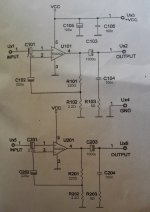
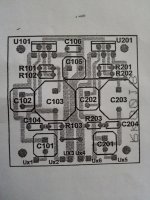
I attached the schematic and PCB layout. Could you please advise how to solve this problem?
Regards,
I built a stereo amplifier using 2 TDA2003 chips but it has 2 problems:
1. I measured around 2V DC at input connector, so I cannot connect the audio source (phone) because it would burn it.
2. The chips begin to heat a lot after connecting the board to supply power (even with no input or load attached). According to datasheet, the quiescent current should be 50mA, so it shouldn't heat too much.
Maybe the second problem is derived from the first one, as the circuit will try to amplify the input voltage.
I even changed the input capacitor to ceramic instead of electrolytic, but I still have DC voltage at input connector, I don't understand what could induce that voltage.
I attached the schematic and PCB layout. Could you please advise how to solve this problem?
Regards,
Attachments
It sounds like the amplifier is oscillating (unstable) and that could cause voltage to show (as measured on a DVM) at the input.
A scope check would confirm this.
If you look at the data sheet you will see that some versions of the circuit have a cap and resistor network across the 220 ohm feedback resistor. That might be worth trying as a test.
Also the data sheet seems to show 1 ohm and 100nF for the Zobel network. Does your 5 ohm get hot ?
Also before doing anything... try shorting the input to ground on both channels. The amp might just be going crazy with a floating input. And fit the correct cap at the input and leave it at that.
Add to Mooly's suggestion, that the input has no resistor to ground, and measuring DC voltage, it is only the tiny leakage thought the input caps, and from this point of view, no abnormal at all.
The overheating of this amps, as he said, maybe the auto oscillation, or perhaps fake chips. Are you using STM or other confidable brand for them?
The overheating of this amps, as he said, maybe the auto oscillation, or perhaps fake chips. Are you using STM or other confidable brand for them?
I remade the PCB and placed the components as much as possible as in the datasheet and now it's working quite fine - no more input voltage or heating when nothing is played.
The only difference is that the input capacitor I chose is non-polarized.
When no song is played I hear the 50Hz wave, but it stops when the song begins.
So yes, the input must be connected to ground with a resistor of about 1k to remove floating or capturing noise signals.
I usually don't buy diy kits and make my own PCBs instead, but I had this kind of issues in the past with TDA2003 and hoped that the kit would be faster to use. So, no more kits from now on.
Thanks guys for your support!
Don't forget that the natural input of the TDA is above 1M, so noise is very capable of being picked up. Perhaps 1K is too low, try 100K. Also, sometimes,a small 100pF to 470Pf short circuits many AM or FM signals preventing malfunction.
That the use of non polar caps is the cause of the problem, is not credible. Surely another hidden error or mistake is in the old board. I use them with 1µF 63V Philips (Oranges) cap, since near 20 year with no trouble.
That the use of non polar caps is the cause of the problem, is not credible. Surely another hidden error or mistake is in the old board. I use them with 1µF 63V Philips (Oranges) cap, since near 20 year with no trouble.
- Status
- This old topic is closed. If you want to reopen this topic, contact a moderator using the "Report Post" button.