Nicely done. That's a quality build right there. I especially like how you supported the Modulus-286 boards along their front edge with standoffs (which is exactly as I intended it). Thanks for sharing.
Should you feel like a pair of blue power supply boards you know where to find them...")
I also note that there's room for the ISS by the mains inlet. Of course, the ISS wasn't available when you started building, but it's an option now.
Tom
Should you feel like a pair of blue power supply boards you know where to find them...
I also note that there's room for the ISS by the mains inlet. Of course, the ISS wasn't available when you started building, but it's an option now.
Tom
Anand,Hi again!
I'm sure a few of you are procrastinating as I had with completing a Modulus 286 build. Well, perhaps this post will serve as an impetus for you folk that need that encouraging boost
Pretty self explanatory (you can click on each of the photos to enlarge them):
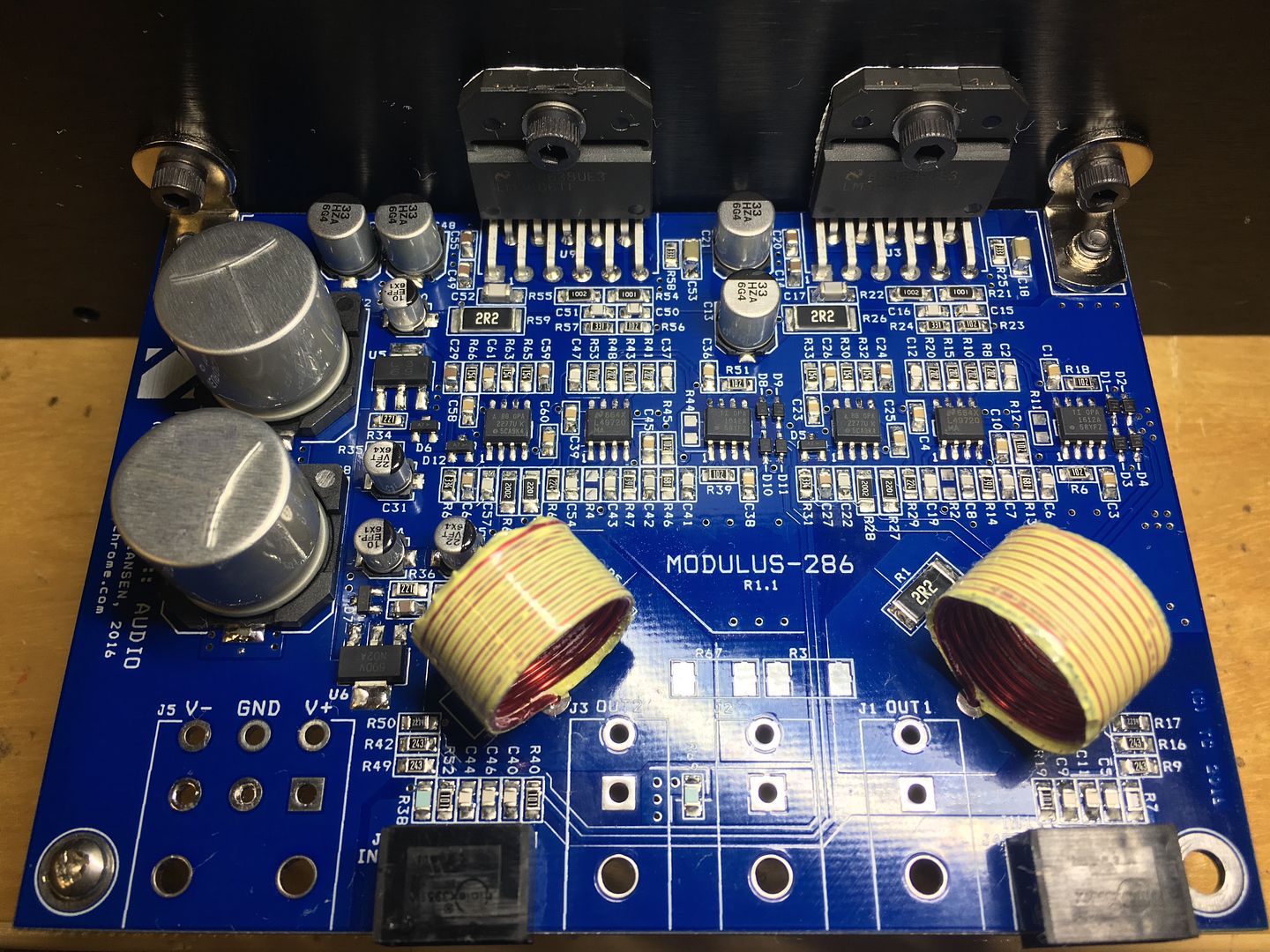
Over 170 SMD parts/board - loved the experience!
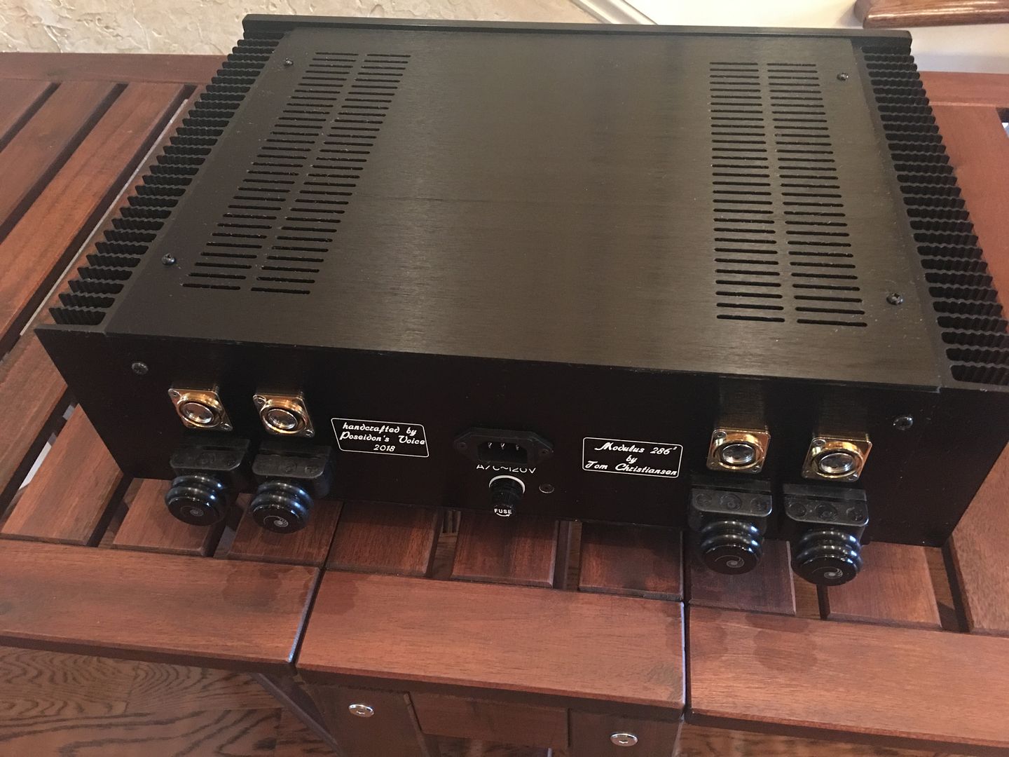
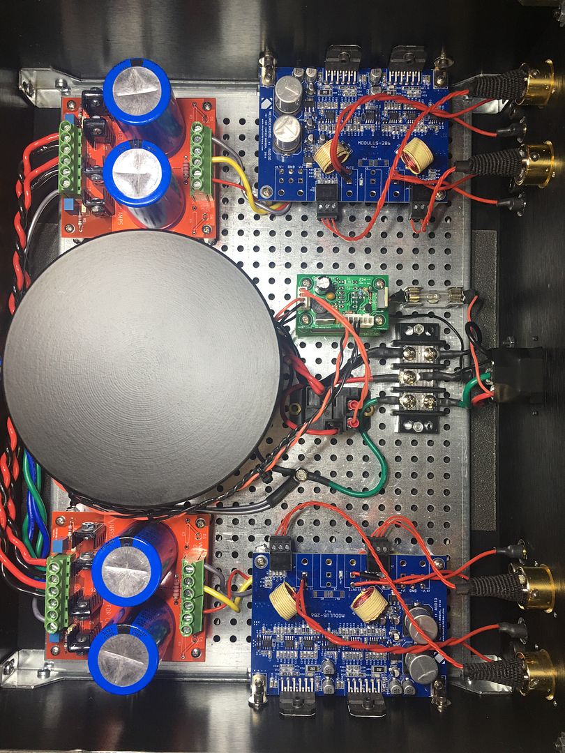
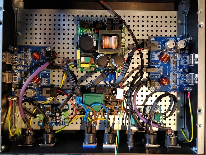
A lot going on here. 300VA transformer with electrostatic shielding and a steel enclosure. AMB Epsilon 24 board for momentary switches w/relay. 2 PS boards, a total of 88,000 uf of capacitance. 4 channel Modulus 286 build, hence the name Modulus 286^2.
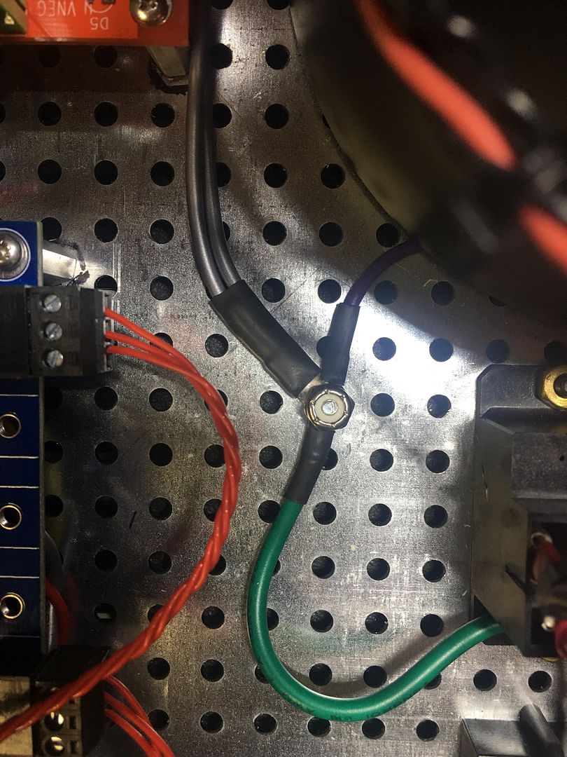
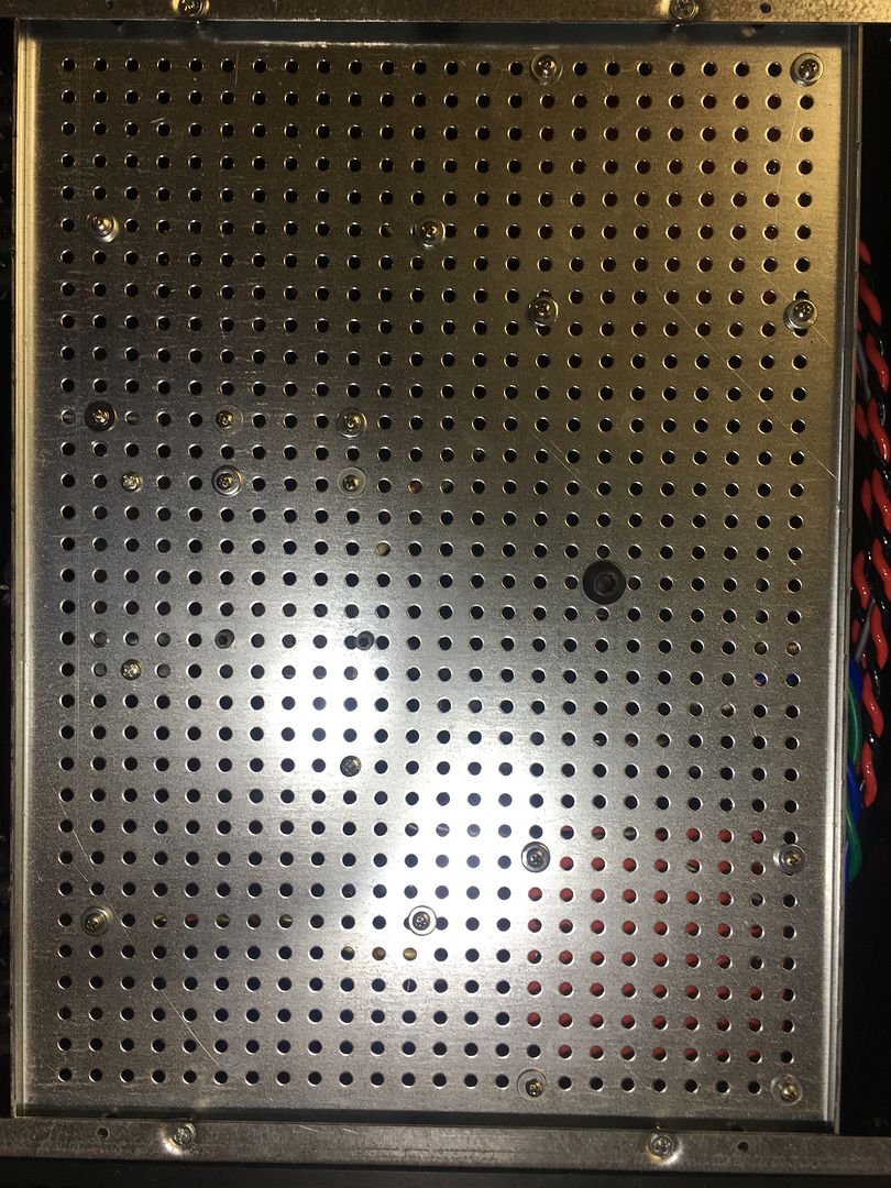
Chassis ground - single most important part of the build; complete with a locknut for safety
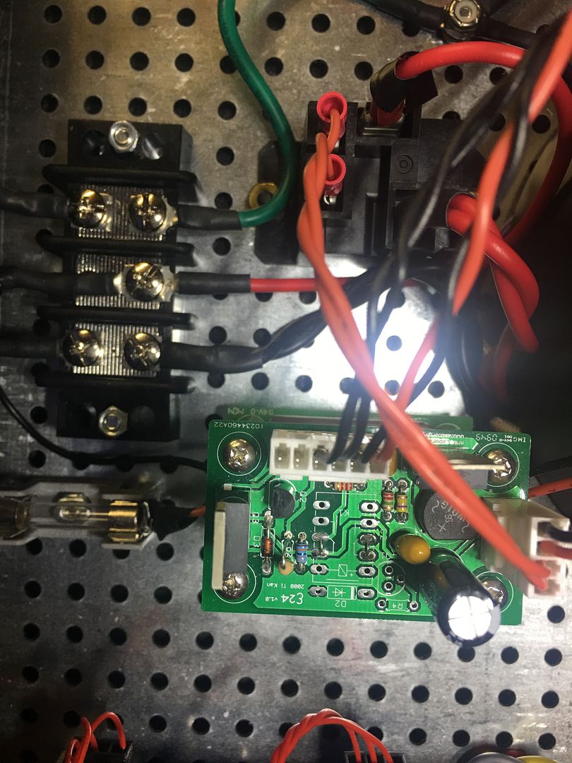
Closeup of the AMB Epsilon 24 board with relay.
When I first fired it up, DC offset on the speaker outputs initially measured about 0.13 mV for all the channels. Within about 30 seconds however, they all drifted down very close to 0mV on my Fluke 87. In late winter 2017, I built a precision 1khz oscillator (2ppm) from AKITIKA that has proven to be useful for my amp builds. It measures about 1.006 kHz and set to an output of 99 mV, I measured between 990 mV to 1010 mV on each of the Modulus 286 outputs confirming my gain setting of 10X (about 20dB to 20.17dB).
What can I say? Precision performance!
Can't wait to put it to the test in my HT setup, these will be powering my L/C/R mains with 1 channel to spare. They are 96dB efficient with an impedance minima of 4.8 ohms, so no worries there
If you have any questions or comments, please don't hesitate to ask. Thanks for reading!
Best,
Anand.


As with all of your projects it is beautifully crafted with great parts and an amazing eye to detail.
I particularly liked your tag on the grounding picture. Too many peopoe say that "it's just the ground" not realizing that that is the most important aspect of any piece of gear.
Fantastic, my friend.

I notice you omitted the pilot LEDs from the PSU boards, a savings of 4 resistors and 4 LEDs. Concerned about too much light inside the chassis?
Yes
As such, I was happy to see that the bleeder resistors function well...in under 10 seconds, the V+/V- rails drain to near zero volts. With the LEDs there would be a visual indicator, but oh well...
Safety first!
Best,
Anand.
Last edited:
Which chassis? While I have no hard data to support the opinion, do you find that the top/bottom covers of the otherwise excellent HiFi200 enclosures could benefit from damping such as from even a few square inches of car audio sound dampening sheet - pick your favourite flavour. With a very high gain circuit using microphonic devices such as a moving coil phono pre-amp with vacuum tubes, enclosure resonance control ain’t no small thing, but with amps such as these, is it perhaps merely academic /aesthetic?
I recently built a pair of ACA for DaveD, and with approx 4 sq in per cover plate, the dull thonk just seemed to more scream “ solid build, dude” than without.
Yes, I know small things, small minds - I should probably get that tattooed on my sternum as a reminder - in reverse, as no one will see it except the guy looking in the mirror while shaving
With a very high gain circuit using microphonic devices such as a moving coil phono pre-amp with vacuum tubes, enclosure resonance control ain’t no small thing, but with amps such as these, is it perhaps merely academic /aesthetic?
In a solid state amp of a decent design, I would argue that the "enclosure resonance control" measures that some manufactures use are entirely marketing.
Now, that said, the automotive damping sheets are pretty heavy, so the enclosure will feel nice and heavy. Heavier objects are perceived (by males) as being of higher quality than lighter objects (yes, there's science to back this up). So maybe you could demand more money for an amp that has a sheet of rubberized lead in it. It also wouldn't surprise me if the resulting 'dead' panel would be perceived as more of a "solid build", hence, a higher quality product. I'm not sure if that has been studied scientifically, though. Gotta love consumer psychology.
Tom
Which chassis? While I have no hard data to support the opinion, do you find that the top/bottom covers of the otherwise excellent HiFi200 enclosures could benefit from damping such as from even a few square inches of car audio sound dampening sheet - pick your favourite flavour. With a very high gain circuit using microphonic devices such as a moving coil phono pre-amp with vacuum tubes, enclosure resonance control ain’t no small thing, but with amps such as these, is it perhaps merely academic /aesthetic?
I recently built a pair of ACA for DaveD, and with approx 4 sq in per cover plate, the dull thonk just seemed to more scream “ solid build, dude” than without.
Yes, I know small things, small minds - I should probably get that tattooed on my sternum as a reminder - in reverse, as no one will see it except the guy looking in the mirror while shaving
Chris,
I complete agree with Tom's response above. That being said, it did irk me to hear a 'ping' sound every time I fastened the covers of the enclosure. As such, I had this in my stable and it killed the 'ping' sound. Installed on both the top and bottom covers. And now I have a solid 'thud'.
Yes it's a small thing.
But it can render a more stable mind.
Best,
Anand.
on the ACA, it only took about scraps of about 2 inches square to deaden the ping
Anand - which chassis was that?
This
10mm Aluminum front panel and Aluminum covers
Steel baseplate
300 mm depth
Best,
Anand.
Nice.
Although I never had any pops during power on / off. At least not if I switch on the source first and even then it’s barely audible.
I always power up from the source to the speaker and power down from the speaker to the source. No pops here.
If you leave the power amp on and turn on the source, you'll likely get a pop as the source's output comes up. There's really no way around that. After all, a pop caused by the source powering up is indistinguishable from any other signal from the power amp's point of view. The amplifier will do its job and amplify the input signal - even if the input is a pop from a source powering up.
If I was to design a system from end-to-end, I'd either control the power-up sequence of the various pieces of equipment or have each output feature a mute switch. There are advantages and drawbacks of both of these approaches.
It's good to see the Guardian-86es being put to good use, though. Thanks for sharing your build pictures.
Tom
The problem I had was at power off. When the preamp triggered the power amp, the power amp powered down more slowly that the preamp. One solution would be to delay the preamp power down which would require a firmware change to the control board I am using. Since that is not possible yet, the Guardian-86 fixes it by muting the speakers quickly enough.
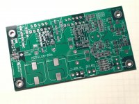
Some... I took delivery of the prototype boards a couple of days ago. See attached (pardon the crappy cell phone picture). I haven't had a chance to do much other than admire their beauty. The coming week will be insane, so don't expect anything to happen until October.
I'm planning to have these tested and available for purchase (at least open up for pre-orders) by the middle of November. I'd like to hit the US Thanksgiving shopping extravaganza.
The prototype boards are green ('cause it's lower cost). The final boards will be blue and gold plated. They'll be available in two options:
1) SMD pre-populated.
2) Fully built and tested module.
Tom
Attachments
Well... It'll be October before I'll have time to push on that project. Assembly takes 2-3 weeks. PCB manufacturing takes two weeks. So realistically, I'll deliver a stack of PCBs and a box of components to my assembly house by early/mid November and open up for pre-orders then. I'll start shipping the SMD-prebuilt option in early December.
The lead time on the mechanical bits I need for the completed module take about a month. I can get those going now so I have them ready when the assembled boards arrive.
I think this timing is realistic. It does assume that prototyping goes well, which I expect it to.
Tom
The lead time on the mechanical bits I need for the completed module take about a month. I can get those going now so I have them ready when the assembled boards arrive.
I think this timing is realistic. It does assume that prototyping goes well, which I expect it to.
Tom
- Status
- This old topic is closed. If you want to reopen this topic, contact a moderator using the "Report Post" button.
- Home
- Amplifiers
- Chip Amps
- Mod-286 build thread