Hello everybody.
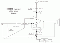
I'm working in a new inverted gainclone following the schematics in the Decibel Dungeon site. I've made a PCB with an Edding, and after soldering the components (standard cheap electrolytics and 5% resistors) mesured the DC offset 23mV. Seems Ok, so I plugged my old speakers and the sound filled the room.
The only issue I have is a very evident distortion in the highs. Thinking it could be the input capacitor, I replaced my 4.7 uF electrolytic by an ceramic 100pF I had, and with a 1uF MKT. The distortion reduced but still remains a little. I'm having the same issues in the two channels.
I tried without input cap and I replaced the 56K (input to ground) with a 100K potentiometer without success. I even addedd a ceramic 220pF to bypass the potentiometer (to filter RF).
I think there's no problem with the grounding because I can't hear any hum at all.
Can someone help to diagnose which can be the causes of the distortion in the highs. Must I replace the resistors with something better?
Thank you.
Have you access to an oscilloscope to see if the amp is oscillating?
Have you used the zobel network on the output?
It may be that as a simple check for oscillation, you could put a low-power 8.2R resistor as the load, and see if it gets warm with no signal applied at the input.
Have you used the zobel network on the output?
It may be that as a simple check for oscillation, you could put a low-power 8.2R resistor as the load, and see if it gets warm with no signal applied at the input.
No, I have'nt an osciloscope, tonight I'll try your suggestion, but without signal there's no hum at all, even putting my ears near the loudspeakers.
I have no zobel between output and ground. In the Nuuk's schematic the zobel is between the power ground and the mains ground (10R2W and 100nF in paralel) . By error I'm taking the loudspeaker's ground from the mains side of this zobel. I'll try to change this.
I have no zobel between output and ground. In the Nuuk's schematic the zobel is between the power ground and the mains ground (10R2W and 100nF in paralel) . By error I'm taking the loudspeaker's ground from the mains side of this zobel. I'll try to change this.
In the Nuuk's schematic the zobel is between the power ground and the mains ground (10R2W and 100nF in paralel) .
It is? I used the zobel on the Gaincloned A60 and it was fitted between the speaker terminals with the cap and resistor in in series not parallel .
No wonder you have some problems
Nuuk , excuse-me for misunderstanding you, but I followed this schematic from your site.
Indeed, you have misunderstood my friend!
That cap and resistor make up a filter. The filter is in the link between the casing or shielding and the power star ground. The filter is there to filter out anything (RFI) picked up by the metal casing/shielding.
The Zobel filter on the output of the amp is there to help the amp cope with speakers that have (widely) varying impedances at different frequencies.
You can try your amp without a Zobel and if it works OK, then you don't need it.
Thank you for your help!!
I corrected the wrong wiring in the loudspeaker's ground and the highs sounds way better.
Now there's only a little distortion but a really very high listening levels. I've tried to put a zobel network between the outputs using a 10Ohm resistor and a cap in series (tried 100nF and 1uF) without changes.
I placed a 8Ohm resistor without signal to test for oscilation, as suggested by Ouroboros, but it does'nt heat at all.
I'll try to get better components, but by the way do you have any suggestions?
I think I could live with it, but we all wanna go further ;-)
- Status
- This old topic is closed. If you want to reopen this topic, contact a moderator using the "Report Post" button.
- Home
- Amplifiers
- Chip Amps
- Gainclone distorting in the higher frequencies
