Alright just to get my thoughts together for my own sake I'm going to write down what my current plan is. I am going to use the Chinese lm1875 boards and resistors. I will replace the chips that came with them with genuine lm1875's. I can post pics of the chinese chips when the boards show up later today if anybody wants. I plan to replace all capacitors that came with the boards because it won't cost very much and if I'm going to put the effort into building a case for this I want to get the best audio quality and longevity as possible. I plan to use ceramic X7R caps upon AndrewT's recommendation for C4(zobel), C5 and C6(decoupling). I have 2.2uf Panasonic film caps I'm going to use for C1(input) which is the recommended value according to the datasheet. This is the same capacitor that's used in the Chipamp lm1875 kit.
http://chipamp.com/docs/lm1875-manual.pdf
I have been comparing the schematic I have for the chinese kits with the Chipamp kit, the lm1875 datasheet, and the discountinued gobo lm1875 kit.
Gobo Stereo Audio Amplifier Kit (LM1875, 15W, Class-AB) - Review
The gobo, chipamp, and datsheet schematics all use a 22uf cap for C3(feedback) which ivanlukic also seemed to recommend so I have chosen to use this value as well. I have decided to use a Nichicon Muse ES 22uf 50V cap for this which is the same one used in the gobo kit. Now as for C7 and C8(decoupling) there are a few different values recommended. According to replies to this thread:
http://www.diyaudio.com/forums/chip-amps/81336-lm1875-power-supply-capacitors.html
It seems that the 100uf figure recommended in the datasheet is a minimum. On my Chinese schematic 220uf caps are listed and with the gobo 330uf caps were used. I plan to use the same kind of Nichicon Muse FG brand caps used with the gobo but with a 50V rating and I'm not sure which capacitance value to go with so recommendations are welcome.
I am going to be using the power supply board from the chipamp kit along with an Antek 100VA 18-0-18v transformer. I have the Panasonic 1500uf 50V caps used with the chipamp power supply but from AndrewT's posts along with many other's it seems that larger caps would be beneficial. For this reason I'm considering replacing these caps with Panasonic 4700uf caps wich have the same lead spacing. This is the same sized cap used in the gobo power supply but they were rated at 50V and digikey only has these with a 35V rating although that would probably be enough. If I went with these power supply caps my setup would be very similar to the gobo's but on the chipamp power supply board I have there is space for snubbers... I have Vishay 0.1µF polypropylene caps I could use for snubbing with 1ohm 2W resistors but I'm not sure if that would be appropriate.
To recap I'd like to know what size caps to use for decoupling on the amp board (100uf,220uf,330uf) and what size caps to use on the power supply board (1500uf,4700uf, or larger?) and whether I should include snubbers.
http://chipamp.com/docs/lm1875-manual.pdf
I have been comparing the schematic I have for the chinese kits with the Chipamp kit, the lm1875 datasheet, and the discountinued gobo lm1875 kit.
Gobo Stereo Audio Amplifier Kit (LM1875, 15W, Class-AB) - Review
The gobo, chipamp, and datsheet schematics all use a 22uf cap for C3(feedback) which ivanlukic also seemed to recommend so I have chosen to use this value as well. I have decided to use a Nichicon Muse ES 22uf 50V cap for this which is the same one used in the gobo kit. Now as for C7 and C8(decoupling) there are a few different values recommended. According to replies to this thread:
http://www.diyaudio.com/forums/chip-amps/81336-lm1875-power-supply-capacitors.html
It seems that the 100uf figure recommended in the datasheet is a minimum. On my Chinese schematic 220uf caps are listed and with the gobo 330uf caps were used. I plan to use the same kind of Nichicon Muse FG brand caps used with the gobo but with a 50V rating and I'm not sure which capacitance value to go with so recommendations are welcome.
I am going to be using the power supply board from the chipamp kit along with an Antek 100VA 18-0-18v transformer. I have the Panasonic 1500uf 50V caps used with the chipamp power supply but from AndrewT's posts along with many other's it seems that larger caps would be beneficial. For this reason I'm considering replacing these caps with Panasonic 4700uf caps wich have the same lead spacing. This is the same sized cap used in the gobo power supply but they were rated at 50V and digikey only has these with a 35V rating although that would probably be enough. If I went with these power supply caps my setup would be very similar to the gobo's but on the chipamp power supply board I have there is space for snubbers... I have Vishay 0.1µF polypropylene caps I could use for snubbing with 1ohm 2W resistors but I'm not sure if that would be appropriate.
To recap
I'd like to know what size caps to use for decoupling on the amp board (100uf,220uf,330uf) and what size caps to use on the power supply board (1500uf,4700uf, or larger?) and whether I should include snubbers.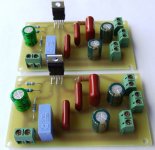
use X7R for supply rail decoupling............... I plan to use ceramic X7R caps upon AndrewT's recommendation for C4(zobel), C5 and C6(decoupling).
Do not use X7R for an amplifier Output Zobel. Use a cap that has high ripple capacity and high voltage rating.
If there is oscillation on the output the voltage peaks can exceed the supply rail voltage by a large margin.
I use 250V MKT but for a +-35Vdc chipamp you should manage with any film cap rated at 120Vdc (two times rail to rail + 50%) or higher.
All the other thoughts are down to choice, I just don't happen to agree with many of those choices.I have 2.2uf Panasonic film caps I'm going to use for C1(input) which is the recommended value according to the datasheet. This is the same capacitor that's used in the Chipamp lm1875 kit.
http://chipamp.com/docs/lm1875-manual.pdf
I have been comparing the schematic I have for the chinese kits with the Chipamp kit, the lm1875 datasheet, and the discountinued gobo lm1875 kit.
Gobo Stereo Audio Amplifier Kit (LM1875, 15W, Class-AB) - Review
The gobo, chipamp, and datsheet schematics all use a 22uf cap for C3(feedback) which ivanlukic also seemed to recommend so I have chosen to use this value as well. I have decided to use a Nichicon Muse ES 22uf 50V cap for this which is the same one used in the gobo kit. Now as for C7 and C8(decoupling) there are a few different values recommended. According to replies to this thread:
http://www.diyaudio.com/forums/chip-amps/81336-lm1875-power-supply-capacitors.html
It seems that the 100uf figure recommended in the datasheet is a minimum. On my Chinese schematic 220uf caps are listed and with the gobo 330uf caps were used. I plan to use the same kind of Nichicon Muse FG brand caps used with the gobo but with a 50V rating and I'm not sure which capacitance value to go with so recommendations are welcome.
I am going to be using the power supply board from the chipamp kit along with an Antek 100VA 18-0-18v transformer. I have the Panasonic 1500uf 50V caps used with the chipamp power supply but from AndrewT's posts along with many other's it seems that larger caps would be beneficial. For this reason I'm considering replacing these caps with Panasonic 4700uf caps wich have the same lead spacing. This is the same sized cap used in the gobo power supply but they were rated at 50V and digikey only has these with a 35V rating although that would probably be enough. If I went with these power supply caps my setup would be very similar to the gobo's but on the chipamp power supply board I have there is space for snubbers... I have Vishay 0.1µF polypropylene caps I could use for snubbing with 1ohm 2W resistors but I'm not sure if that would be appropriate.
To recap
Not fake LM1875s, but used!
I agree, I seldomly buy key parts on ebay or such. But I saw this kit tested by JohnAudioTech on youtube. These chips are actually genuine, but they are not new! They were probably used in a now obsolete product, desoldered and repurposed.
I have no problem with that. Bought 6 of these kits on Ebay, for this price (about 3 euro shipping included) you can't go wrong.
The big problem with the china’s kits is "fake chips".
I agree, I seldomly buy key parts on ebay or such. But I saw this kit tested by JohnAudioTech on youtube. These chips are actually genuine, but they are not new! They were probably used in a now obsolete product, desoldered and repurposed.
I have no problem with that. Bought 6 of these kits on Ebay, for this price (about 3 euro shipping included) you can't go wrong.
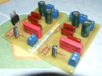
I more or less only used the boards, so even if the chips may be genuine but used I had them replaced. Some Elnas, Panasonic and Kemet as well.
And I didn't follow the kit's schematic either...


Sounds better than the polish ones I tried first.
Had someone call my cell when I held it between the heatsinks and all ok.
And I didn't follow the kit's schematic either...
Sounds better than the polish ones I tried first.
Had someone call my cell when I held it between the heatsinks and all ok.
Last edited:
Also, I'd like to ask, which one of these is a good pot for this amp?
https://www.arrow.com/en/products/rk09712200mc/alps-electric
https://www.arrow.com/en/products/p092n-qc15ar20k/bi-technologies
https://www.arrow.com/en/products/pdb182-k430k-503a/bourns
https://www.arrow.com/en/products/ptr902-2020f-a503/bourns
https://www.arrow.com/en/products/rk09712200mc/alps-electric
https://www.arrow.com/en/products/p092n-qc15ar20k/bi-technologies
https://www.arrow.com/en/products/pdb182-k430k-503a/bourns
https://www.arrow.com/en/products/ptr902-2020f-a503/bourns
Last edited:
How do you think it sounds?
I am a little bit worried about the chip as well, the legs are so flimsy.
I am ordering some caps also for this build.
I'm impressed that it sounds so good and yet it could probably benefit from a better power supply. I have cheap EI-transformers and very simple rectifier boards.
Next step for me is to add a fixed voltage divider instead of volume pot.
Also change C1 from electrolyte to a poly film cap.
Maybe maybe test with slightly lower gain since I only use 12 Vac.
Would like to soften the highs a little bit, but not shure, it's maybe my pre amp...
I built LM1875 circuit from the manufacturer DS schematic using 22uF in the feedback lag. This kit already uses more - 47uF. I tried it on my friend's Harbeth Super HL5 + loudspeaker, which is high end speaker, and there was no deficit in the low octaves even with 22uF in the feedback lag. LM1875 just played fine.
Of course, you can buy more expensive parts and use them, but this is not some High End circuit in the first place and I think that it would play just fine even with parts supplied with kit.
Folks, I am quoting Ivan but this is a general question: Could it be that the 22uF mentioned above is a bipolar cap? I read elsewhere in the forum that Andrew wrote this could be 22uF of small voltage rating, like 16V. Anyone can confirm that? If I use 2.2uF input cap would 22uF BP cap work in this position?
Thank you.
I'm impressed that it sounds so good and yet it could probably benefit from a better power supply. I have cheap EI-transformers and very simple rectifier boards.
Next step for me is to add a fixed voltage divider instead of volume pot.
Also change C1 from electrolyte to a poly film cap.
Maybe maybe test with slightly lower gain since I only use 12 Vac.
Would like to soften the highs a little bit, but not shure, it's maybe my pre amp...
Glad that you're impressed with it. Did you use the chip that came with the kit?
Also which R sets the gain? I am looking into using a lower gain as well. Maybe 18x is good? Thanks again.
No, I had chips at home which I know are genuine instead of taking a chance with the kit's chips.
People here has tought me that R3 (22K) and R4 (1K) sets the gain.
R3+R4/R4 so 22+1 is 23 and /1 makes 23. If I'm not mistaken it's voltage gain, so in decibels a little more (?)
It's the top two resistors on the board to the left of the chip.
Anyway... some seems to recommend balancing the input impedance if you change above feedback resistor value. I don't know how important that is, but I try to follow that suggestion.
But actually I don't understand how resistors in parallell can balance resistors in series (same values), but perhaps someone else can explain that.
As for C3, again others say that its a DC blocking cap, but also makes a highpass filter together with R4. 22uf with 1K makes 7.2 Hz according to my nifty little app
This cut off frequency should be lower than the cut off at the input.
My input has C1 (2.2uf) with R2 (20K) ~ 3.6 Hz so therefor I chose 100uf for my C3 to get 1.6 Hz.
There is also a lowpass filter at the input, to reduce interference from high frequency stuff. This time that cut off frequency should be lower than the zobel at the output.
The input should set the bandwidth you want, the other 2 filters should be "outside" that input bandwidth.
Check online for a RC Filter calculator. R (resistor) C (cap.) hence the name.
Also you get bits and pieces in all the other threads here about the LM1875.
Together with the different opinions, so a little trial & error is maybe necessary anyway.
Edit: C3 is from a picture of the board... it's C2 in the schematic I followed. Sorry.
Last edited:
Folks, I am quoting Ivan but this is a general question: Could it be that the 22uF mentioned above is a bipolar cap? I read elsewhere in the forum that Andrew wrote this could be 22uF of small voltage rating, like 16V. Anyone can confirm that? If I use 2.2uF input cap would 22uF BP cap work in this position?
Thank you.
Data Sheet schematic for LM1875 shows correct polarity orientation for the feedback cap if ordinary elco is used, but there is no reason why the same value (22uF) bipolar elco cannot be used in that position too. It's just that small bipolar elcos are more difficult to find. 16V rating for that cap is fine.
@Hedliden: Thank you for sharing. From what I've read, too low of a gain is not good for these amps. I think I will follow the stock 23dB gain. Input cap is 2.2uF so I'll go with 100uF for C3 as well. I am looking and comparing Wima and Panasonic film caps, especially Wima MKS2 (polyester, 63V) and Panasonic ECW (polypropylene, 450V) From dielectric and voltage rating side, Panasonic is superior. Can anyone tell me why I should go with Wima instead? Size is also no problem, ECW has small pitch as well.
You're right, it is hard to find. I will use 100uF instead as calculated in page 2Data Sheet schematic for LM1875 shows correct polarity orientation for the feedback cap if ordinary elco is used, but there is no reason why the same value (22uF) bipolar elco cannot be used in that position too. It's just that small bipolar elcos are more difficult to find. 16V rating for that cap is fine.
Thanks!Further more, I'm even more impressed now that I've sorted out my speakers...
I have old Proson Conquest 6030 mkII that I fitted with new Monacor DT-254 tweeters.
They are a little more sensitive than the originals and the speakers were a little shouty from the beginning.
After reading a thread here about making/tweaking crossovers without measuring equipment... I tried this: I lowered all frequencies over 2000Hz in my digital equalizer (in my mp3 software). The tweeters are cutoff a little higher, but I went from 2KHz anyway. I lowered 3dB on all sliders and it sounds great now
Last edited:
- Status
- This old topic is closed. If you want to reopen this topic, contact a moderator using the "Report Post" button.
- Home
- Amplifiers
- Chip Amps
- Chinese Mono LM1875 Board