If I was building a few amps I would leave these parts off.
a 4 to 10 ohm 1/4 W resistor for 1W app is plenty.
Its a one off spare parts project using a chip I found in my box so I'll include it as an experiment, its kind of exciting doing things that I've not done before.
Bet its been a while since most people here have gotten excited about an output inductor
Could I use a 10 ohm 1/10th watt resistor to save space or is that likely to get too hot?
hard to tell.
it may, but usually we like em to be hihger watts.. space saving was woundng the inductor around the resistor it self.
I guess I'll just use 1/4w and stand it upright, should only take 2 hole spaces wide in the tripad board then.
A 1/10 watt resistor?? Are you sure?
Remember that its only a 1w TDA2822m chip amp being powered with 12v max and not a big 50w hifi system.
Nonsense.This requirement to pass HF & RF demands an ultra low trace/cable impedance
The typical Zobel resistor is 10 ohms.
Some go as low as 1 ohms.
So no need to overworry about "ultra low impedance"
Whether you place it across speaker out and ground pins at a chipamp footprint or across speaker out connector 2 to 4 inches away is the same,the possible 0.02 ohm or lower resistance in between will not matter.
Possible significant cable capacitance will mean something at least a few meters away, definitely not centimeters away.
As of being on one side or the other of an output capacitor, if it has zero impedance, either side is the same by definition; if it has significant impedance then it will be isolating cable capacitance on its own, so it´s clear that it´s not a problem by itself.
the output coil is there to help isolate cable capacitance from the output stage. Capacitance loading of the output changes the stability margins and can make an amplifier ring or worse oscillate.
But zero loading by disconnecting the loudspeaker cables leaves the amplifier without any defined load and some can become less stable in this condition. Adding an Output Zobel gives the amplifier a defined HF load to help control the amplifier behaviour.
BUT !
the amplifier Output Zobel can only pass high frequencies. Much higher than the audio band and into the RF region. This requirement to pass HF & RF demands an ultra low trace/cable impedance and that equates to fitting the smallest components with the shortest leads/traces around the output device/s
I think you have got your capacitance and inductance mixed up.Nonsense.
The typical Zobel resistor is 10 ohms.
Some go as low as 1 ohms.
So no need to overworry about "ultra low impedance"
Whether you place it across speaker out and ground pins at a chipamp footprint or across speaker out connector 2 to 4 inches away is the same,the possible 0.02 ohm or lower resistance in between will not matter.
Possible significant cable capacitance will mean something at least a few meters away, definitely not centimeters away.
As of being on one side or the other of an output capacitor, if it has zero impedance, either side is the same by definition; if it has significant impedance then it will be isolating cable capacitance on its own, so it´s clear that it´s not a problem by itself.
If you want the Amplifier Output Zobel to effectively load the output at frequencies approaching RF then one needs ultra low impedance.
Guys, I think some of us are getting confused.
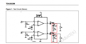
By zobel network I'm only referring to the Boucherot cell as shown in the example circuits of the datasheets and not the optional extras that many people here include.

Non of my speakers have any extra components across the terminals so all of the HF filtering is done on the circuit board by the RC Boucherot cell at the output of the chip.
So just to confirm its better to put R3, R4, C6, C7 before C4 and C5? That is connecting directly to pins 1 and 3 and ground.
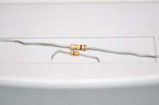
They are through hole carbon film and are about half the size of regular 250mW resistors, usually found in cheap Chinese equipment which is where I pulled them from.

By zobel network I'm only referring to the Boucherot cell as shown in the example circuits of the datasheets and not the optional extras that many people here include.

Non of my speakers have any extra components across the terminals so all of the HF filtering is done on the circuit board by the RC Boucherot cell at the output of the chip.
So just to confirm its better to put R3, R4, C6, C7 before C4 and C5? That is connecting directly to pins 1 and 3 and ground.
The only 0.1W resistors I'm aware of are SMD. It's going to have to be a reasonable size to wind a coil round it, anything smaller than 1W is going to be very fiddly
They are through hole carbon film and are about half the size of regular 250mW resistors, usually found in cheap Chinese equipment which is where I pulled them from.

It's to ensure stability, so place it as close to the amplifier output as possible.................If you plan to run/test at high power/frequency, use a Zobel resistor of several Watts rating.
It is an HF load on the amplifier. ...............That requires the amplifier Output Zobel to be VERY close to the output and input pins.
Fig 12 is the correct placing...............
Thanks everyone, it looks like I'll connect it directly to the output pins then....................
Neither you nor the Members are confused. The Amplifier Output Zobel is the R+C placed on the Output of the amplifier.Guys, I think some of us are getting confused.
The R+C is the amplifier output ZobelBy zobel network I'm only referring to the Boucherot cell as shown in the example circuits of the datasheets
Almost no manufacturer/Designer offers a power amplifier that is stable for all loading conditions and omits the Output Inductor. I know of at least one Designer mentioned in this Forum that does omit this stability component. But they are probably alone in doing so.and not the optional extras that many people here include.
In my (amateur) view the output inductor is not an optional component. Low current outputs can save money by replacing the damped inductor with a single resistor and you will often see this recommended in opamp datasheet and ap notes.
Then that points to penny pinching and hoping not too many come back under warrantyView attachment 619798
Non of my speakers have any extra components across the terminals so all of the HF filtering is done on the circuit board by the RC Boucherot cell at the output of the chip.
You got four Members' replies confirming this.So just to confirm its better to put R3, R4, C6, C7 before C4 and C5? That is connecting directly to pins 1 and 3 and ground.
don't use those tiny carbon film resistors.They are through hole carbon film and are about half the size of regular 250mW resistors, usually found in cheap Chinese equipment which is where I pulled them from.
View attachment 619811
- Home
- Amplifiers
- Chip Amps
- Zobel network placement