I'm trying to amplifie a plain dc signal, the signal is 0.2V and i'm tring to light a led that needs 1.5V.
I tried doing it with the LM386 and cant get an output.
I built the circuits the same as in the pdf file from national
www.national.com/ds/LM/LM386.pdf
If any one can help....

I tried doing it with the LM386 and cant get an output.
I built the circuits the same as in the pdf file from national
www.national.com/ds/LM/LM386.pdf
If any one can help....
The LM386 is a single supply opamp. The circuit in the national datasheet has a DC blocking cap on the input, which is blocking the signal you're trying to amplify. You won't be able to use this for your purposes.
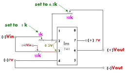
You should use an LM741 instead rigged as a comparator. Since your signal level is only 200mV, your comparator will be kind of touchy. What you need to do is use 2 resistors to make a voltage reference of 100mV at the - input to the 741, connect your input signal to the + input.
You might be able to use the same scheme on the LM386 but it has the gain built in which you can't disable.
--
Danny

Maybe you could share a little more insight and I could provide a little more specific feedback about the type of circuit you'd want. What is the source of your signal that is only 200mV that you want to go to an LED?
Here is a link to a "schmidt trigger" circuit. In all likelyhood this is what you'll want so that you'd avoid noise from glitching around your circuit. You would want to break the threshold pot into 2 resistors instead so that you could hand tune the threshold to 100mV. It's just 2 resistors in series with your input taken from in between them. The values you use depends on your VCC.
http://www.ee.ttu.edu/lab/robot/hyster.htm
I guess you are right, i should start from the begining.
I'm now in my 4th year in the university and my final project is to build a device that can track eye movement in real time, this device is going to be installed in our car simulator inside a lab.
the way it is going to work is by:
1. video signal will enter a chip lm1881 sync separator
2. the lm1881 will give an output of 0.2V whenever an even field is been shot
3. this signal will enter the amp
4. the amp will be connected to a circal of infra red lights
the signal from the lm1881 is going to turn on and off many times in one second
in short what will be is kind of like the red eye effect when using a flash, with this device i will be able to get the red eye effect using infra red light that is not visibale to the driver.
with MatLab it can be very easy to filter the background from the eyes and track them.
in this link you can see what i meen (and in better english") )
)
www.cs.ucsb.edu/conferences/PUI/PUIWorkshop98/ Papers/Morimoto.pdf
I'm now in my 4th year in the university and my final project is to build a device that can track eye movement in real time, this device is going to be installed in our car simulator inside a lab.
the way it is going to work is by:
1. video signal will enter a chip lm1881 sync separator
2. the lm1881 will give an output of 0.2V whenever an even field is been shot
3. this signal will enter the amp
4. the amp will be connected to a circal of infra red lights
the signal from the lm1881 is going to turn on and off many times in one second
in short what will be is kind of like the red eye effect when using a flash, with this device i will be able to get the red eye effect using infra red light that is not visibale to the driver.
with MatLab it can be very easy to filter the background from the eyes and track them.
in this link you can see what i meen (and in better english
)www.cs.ucsb.edu/conferences/PUI/PUIWorkshop98/ Papers/Morimoto.pdf
They shuld all be on the same board, i thought to connect them with a plain wire, not longer then 3cm.
I read the article you sent me about the schmidt trigger.
i have some questions
1. the 200mV comming from the lm1881 i should connect to the non-inverting input?
2. what should i connect to the inverting input?
3. what is V_hysteresis?
I hope you dont find me to much of a nag
I read the article you sent me about the schmidt trigger.
i have some questions
1. the 200mV comming from the lm1881 i should connect to the non-inverting input?
2. what should i connect to the inverting input?
3. what is V_hysteresis?
I hope you dont find me to much of a nag
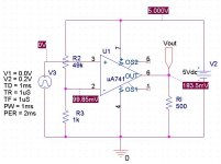
I bought the LM741
made the following circuit and it does not work.
when i am not putting anything in the Vin i get Vout of about 2V
when i do hook up the Vin with 0.2V i get Vout about 6V
when i try to change the 6.5K or the 1k it does not effect the output.
What did i do wrong?
made the following circuit and it does not work.
when i am not putting anything in the Vin i get Vout of about 2V
when i do hook up the Vin with 0.2V i get Vout about 6V
when i try to change the 6.5K or the 1k it does not effect the output.
What did i do wrong?
Attachments
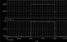
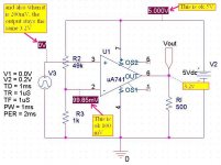
So... the 741 basically compares what it is getting in on the + input against the ~100mV "reference" voltage at the - input. When the + input is larger than the - input, the output goes to the VCC rail. When the opposite condition is true, the output goes to GND. Unfortunately, although cheap, the 741 can't swing rail-to-rail. I forgot about this when I recommended it. However, as you can see it is only limited by about 200mV (this isn't related to your input). This is not enough voltage to turn on your diode so it shouldn't be a problem.
This should be enough to drive a LED, but don't forget to use a current limiting resistor. 220ohms in series with the LED should be fine. If you want to use this circuit to drive your ring of LEDs you'll need a driver after it that can drive more current. Maybe a 74LS245 or 74LS04.
This should be enough to drive a LED, but don't forget to use a current limiting resistor. 220ohms in series with the LED should be fine. If you want to use this circuit to drive your ring of LEDs you'll need a driver after it that can drive more current. Maybe a 74LS245 or 74LS04.

- Status
- This old topic is closed. If you want to reopen this topic, contact a moderator using the "Report Post" button.
- Home
- Amplifiers
- Chip Amps
- Help with LM386N-1 amplifier