Da5id4Vz said:If the bridged amplifier were made out of a cluster of BLB (Brian’s Little Board),
It could be called the Contatenclone. I may be alone in this, but I kind of like the idea of mating the BLB to some form of a motherboard to build bridged amp.
-Dave
That is my intention. See the bridgeclone thread:
http://www.diyaudio.com/forums/showthread.php?postid=352209#post352209
I will be trying it out soon with the DRV134.
Follow up any discussion of this in that thread.
--
Brian
Cappy said:It seems like we should be able to buy a decoding chip that includes the Dolby licensing fee.
Or is this too logical a thought?
But, i believe, against the terms of the licencing agreement.
dave
To Brian GT: Supplied 8 MUR860 and 4 Panasonic cap on the kit, how are they setup?
Hi Brain,
Regarding the power supply part of the kit, are they intended for dual mono supply, each with single diode bridge with 2 caps configuration, or single supply with two bridges and 4 caps?
Thanks,
---
David
Hi Brain,
Regarding the power supply part of the kit, are they intended for dual mono supply, each with single diode bridge with 2 caps configuration, or single supply with two bridges and 4 caps?
Thanks,
---
David
Attachments

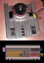
Finally i got something started!. I soldered up a couple of boards just using the provided resistors and some caps i have around.
So thought i would build up the first ones into these 2 "car amp" heatsinks i picked up ages ago and never used. the 2 heatsinks will form the top and bottom of the case (only bottom one shown)
The power and amp section will be completely seperated with a shield (probably from copper as i have some around) the volume pot will have a plastic extender so the volume knob will be on the front. the power plug will be in the side. the thing will look pretty "industrial" anyways so i do not really care about the ugly cord sticking out the side")
this layout will give very short internal cable runs for signal and output, even with the pot. it will also leave room for a better attenuator if i decide to upgrade it. (its alps pot 4x 50k audio taper, but i will parallel 2 gangs per chan for 25k input)
The front and back will just be fabricated from flat material. if it ends up looking nice, and working well I can always upgrade the actual boards to ones with better resistors and capacitors, and there is room for a bigger transormer as well(is just ILP 160VA for now)
but i do have a much nicer case planned for when i have a bit of cash to spend on it. (see render in my icon )
So thought i would build up the first ones into these 2 "car amp" heatsinks i picked up ages ago and never used. the 2 heatsinks will form the top and bottom of the case (only bottom one shown)
The power and amp section will be completely seperated with a shield (probably from copper as i have some around) the volume pot will have a plastic extender so the volume knob will be on the front. the power plug will be in the side. the thing will look pretty "industrial" anyways so i do not really care about the ugly cord sticking out the side
this layout will give very short internal cable runs for signal and output, even with the pot. it will also leave room for a better attenuator if i decide to upgrade it. (its alps pot 4x 50k audio taper, but i will parallel 2 gangs per chan for 25k input)
The front and back will just be fabricated from flat material. if it ends up looking nice, and working well I can always upgrade the actual boards to ones with better resistors and capacitors, and there is room for a bigger transormer as well(is just ILP 160VA for now)
but i do have a much nicer case planned for when i have a bit of cash to spend on it. (see render in my icon
)Attachments
I'm really sorry: on the diode & cap question
Dear Brian,
I'm really sorry that I did not really read all the post, until I tried then, only to find that you already put a user guide for your kit on your website.
I read it through and it already answer my question.
Thanks,
---
David
Once again, really sorry. Also to other members that must see my unusable previous post.
i as well have been planning on setting up a 5.1 (or more) setup for a home theater application. from everything i've found, you must either licence the codec (software) for big money, or use something cheaper. my plan has been to either buy a cheap pc decoder (sometimes found with a good set of pc speakers) or taking out the preamp section of an inexpensive home theater reciever. since i planned on making a seperate preamp, this works out jsut fine for me (probably find some way to incorporate of the good pre's from ESP)
SQ Kid said:i as well have been planning on setting up a 5.1 (or more) setup for a home theater application. from everything i've found, you must either licence the codec (software) for big money, or use something cheaper. my plan has been to either buy a cheap pc decoder (sometimes found with a good set of pc speakers) or taking out the preamp section of an inexpensive home theater reciever. since i planned on making a seperate preamp, this works out jsut fine for me (probably find some way to incorporate of the good pre's from ESP)
I was contemplating on using the Creative DDTS-100 decoder as it decodes basically everything. Should be possible to rip out the guts for a nice clean install into a pre-amp.
neutron7 said:Finally i got something started!. I soldered up a couple of boards just using the provided resistors and some caps i have around.
So thought i would build up the first ones into these 2 "car amp" heatsinks i picked up ages ago and never used. the 2 heatsinks will form the top and bottom of the case (only bottom one shown)
The power and amp section will be completely seperated with a shield (probably from copper as i have some around) the volume pot will have a plastic extender so the volume knob will be on the front. the power plug will be in the side. the thing will look pretty "industrial" anyways so i do not really care about the ugly cord sticking out the side
this layout will give very short internal cable runs for signal and output, even with the pot. it will also leave room for a better attenuator if i decide to upgrade it. (its alps pot 4x 50k audio taper, but i will parallel 2 gangs per chan for 25k input)
The front and back will just be fabricated from flat material. if it ends up looking nice, and working well I can always upgrade the actual boards to ones with better resistors and capacitors, and there is room for a bigger transormer as well(is just ILP 160VA for now)
but i do have a much nicer case planned for when i have a bit of cash to spend on it. (see render in my icon
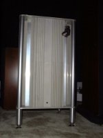
Hey Nuetron I like the Active Surplus Heat sink you got there. I have a few Dozen myself. How many gainclones do you think I could put in this chassis?
Regards
Anthony
Attachments
Coulomb said:
How many gainclones do you think I could put in this chassis?
My guess is that even 20 wouldn't strain the capabilies of that enclosure
Problem here...I finally got around to putting my GC together. I had to improvise for the chassis and ended up using a very old scott stereo chassis that is about 4 times the size I need. Anyway, I'm running ±25v rails from an 18-0-18 center-tapped transformer, using the instructions Brian gave for connecting a CT transformer to the PS board. When I turn it on with no cables on the input, my speakers are completely silent. As soon as I plug in a cable that is connected to a source (or anything else), I get a really obnoxious buzz.
This is how my grounding is configured (I hope text will suffice because I'm not good at drawing pictures). Both grounds come from the PG+ side, as PG- is where the center tap is connected. One ground goes to one of the channels. The other, directly to the star ground. Both channels are connected to the star ground from the CHG connector. I also tried grounding both the PGND leads from the power supply through the amp boards, but I get the same result. A shielded, 4-conductor cable is connected to the input rca jacks, with the shield grounded to the sgnd on one. Then they go to an old alps pot of unknown quality in the front of the chassis, and then onto the boards. All the solder joints appear to be good, both electrically and mechanically, and the everything is a good distance from the (bellybanded EI) transformer. Does anybody have any ideas as to the cause?
This is how my grounding is configured (I hope text will suffice because I'm not good at drawing pictures). Both grounds come from the PG+ side, as PG- is where the center tap is connected. One ground goes to one of the channels. The other, directly to the star ground. Both channels are connected to the star ground from the CHG connector. I also tried grounding both the PGND leads from the power supply through the amp boards, but I get the same result. A shielded, 4-conductor cable is connected to the input rca jacks, with the shield grounded to the sgnd on one. Then they go to an old alps pot of unknown quality in the front of the chassis, and then onto the boards. All the solder joints appear to be good, both electrically and mechanically, and the everything is a good distance from the (bellybanded EI) transformer. Does anybody have any ideas as to the cause?
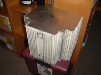
LOL Coulomb. that big active surplus heatsink monster! you could make a zalman style no fans heatpipe PC enclosure with those. or is that what it is
stupid shop is under construction and you cant go into the basement anymore i want some more of those.
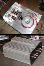
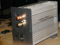
anyways i did more work on it today including external bench testing the amps which work fine!
almost all drilling and tapping is done.
the rear panel was harder because it is aluminium wit 1/4 inch plexi backing for mounting the connectors. you cant really see it in the pics but the actual connectors are attached to the plexi, and the hole in the aluminium is oversize.
all i have to do now is
make a knob extender (lathe)
find or make a knob
make front panel
power and receptacle cutout (carve some hetsink)
wire it up
stupid shop is under construction and you cant go into the basement anymore
i want some more of those.anyways i did more work on it today including external bench testing the amps which work fine!
almost all drilling and tapping is done.
the rear panel was harder because it is aluminium wit 1/4 inch plexi backing for mounting the connectors. you cant really see it in the pics but the actual connectors are attached to the plexi, and the hole in the aluminium is oversize.
all i have to do now is
make a knob extender (lathe)
find or make a knob
make front panel
power and receptacle cutout (carve some hetsink)
wire it up
Attachments
neutron7 said:LOL Coulomb. that big active surplus heatsink monster! you could make a zalman style no fans heatpipe PC enclosure with those. or is that what it is
stupid shop is under construction and you cant go into the basement anymore
anyways i did more work on it today including external bench testing the amps which work fine!
almost all drilling and tapping is done.
the rear panel was harder because it is aluminium wit 1/4 inch plexi backing for mounting the connectors. you cant really see it in the pics but the actual connectors are attached to the plexi, and the hole in the aluminium is oversize.
all i have to do now is
make a knob extender (lathe)
find or make a knob
make front panel
power and receptacle cutout (carve some hetsink)
wire it up
I have an amp that looks virtually the same as yours that I made last year, there are some photo's on this site somewhere.
I had a section of 1x1 seperating the top and bottom halves.
My Tower of Power is yet to find suitable tenants befitting of such a structure.
BTW - Active Surpluas is not renovating, the Property is being split in half and a developer is building on the demolished side. The owners have yet to decide on closing up shop, moving or running as is and maybe opening up the 2nd floor.
Regards
Anthony
Doh. I guess it is a pretty obvious way to build an amp if you have some of those heatsinks
I think you should make a heatpipe cooled PC. it can be totally silent. you can even get passive PSUs and VGA coolers.
Im not talking VIA epia nonsense here either. you could even do it with prescot or AMD 64
you can get 10 heatpipes in the form of "zalman hard drive cooler" from bigfoot for $35
then you will be able to Listen to all the other cool stuff you made while not being interfered with by annoying PC fan noise.
P.S. it would truly be a day if Active decides to close.
I think you should make a heatpipe cooled PC. it can be totally silent. you can even get passive PSUs and VGA coolers.
Im not talking VIA epia nonsense here either. you could even do it with prescot or AMD 64
you can get 10 heatpipes in the form of "zalman hard drive cooler" from bigfoot for $35
then you will be able to Listen to all the other cool stuff you made while not being interfered with by annoying PC fan noise.
P.S. it would truly be a
day if Active decides to close.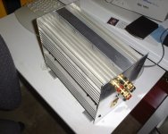
Coulomb thats nice. is it a class a or something to be just one channel and be that large (and not have PSU inside). I bet its got a lot more inside than a couple of tiny 'clones.
did you make the other matching one? or is it for a sub amp or speaker test amp or something like that.
sorry for the OT everyone
did you make the other matching one? or is it for a sub amp or speaker test amp or something like that.
sorry for the OT everyone
Ok, a little more info about my problem. It seems that whenever I connect input cables to a source, whether my DVD player or my HT receiver's output, regardless of whether or not the source is turned on, I get the hum. Neither of these as a 3-prong grounded plug. However, when I connect it to a preamp with a grounded plug, I have no noise at all regardless of whether it's on or off. The obvious solution, then, would be to connect my preamp between the source and amp, but I'd prefer to keep from putting anything else in the signal path if I can help it. Does this mean the buzz is coming from the source? If it were, I would assume that I should also hear it through my HT receiver, but I don't, so the question remains how do I get rid of it?
tpenguin said:Problem here...I finally got around to putting my GC together. I had to improvise for the chassis and ended up using a very old scott stereo chassis that is about 4 times the size I need. Anyway, I'm running ±25v rails from an 18-0-18 center-tapped transformer, using the instructions Brian gave for connecting a CT transformer to the PS board. When I turn it on with no cables on the input, my speakers are completely silent. As soon as I plug in a cable that is connected to a source (or anything else), I get a really obnoxious buzz.
This is how my grounding is configured (I hope text will suffice because I'm not good at drawing pictures). Both grounds come from the PG+ side, as PG- is where the center tap is connected. One ground goes to one of the channels. The other, directly to the star ground. Both channels are connected to the star ground from the CHG connector. I also tried grounding both the PGND leads from the power supply through the amp boards, but I get the same result. A shielded, 4-conductor cable is connected to the input rca jacks, with the shield grounded to the sgnd on one. Then they go to an old alps pot of unknown quality in the front of the chassis, and then onto the boards. All the solder joints appear to be good, both electrically and mechanically, and the everything is a good distance from the (bellybanded EI) transformer. Does anybody have any ideas as to the cause?
- Status
- This old topic is closed. If you want to reopen this topic, contact a moderator using the "Report Post" button.
- Home
- Amplifiers
- Chip Amps
- Gainclone building thread based on BrianGT's boards