Does this DIY stuff ever end or do you just keep doing it?
Kofi [/B]
Unfortunately it's a nasty affliction to shake off.
As for the attenuator - don't worry, there are plenty of people who can help you and the results really are worth more than any fancy cables
")
If you have a look at this website - http://uk.farnell.com/jsp/home/homepage.jsp - (it's a UK one but there is a US version) you can type in the product codes for the bits I used to make mine:
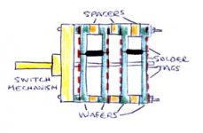
Wafer / Dummy Wafer (146057 / 146059) - these are what you attach the resistors to, the difference between the two is that the dummy wafer has no moving parts (and is a bit cheaper as a result). You only need to change contact with one end of the resistor as you rotate the switch mechanism; the other ends are all connected to signal ground.
Switch mechanism (146046), Spacers (146044). Then once you've put it together you can solder your resistors in place.
Take a look at this diagram (copyright of Nick!)
Attachments
Digi,
Thanks for the schematic. I'm going to investigate all the options for the preamp here, and your schematic looks a bit easier to handle.
I have to admit that I am attracted to the link to the preamp that matjans posted, so I may give that a whirl.
Where did you get your design? Did you design this yourself?
Ropie,
Thanks for all the fantastic information. I am now very interested in getting the parts for the attenuator. I think that Newark In One is the US version of Farnell, so I'll get the stuff from there. Of course, what would my gratitude be without any questions...
I think I'll go with the resistor values posted on Nuuk's site (great site, BTW), and I may go with Riken resistors since that's what's in my GC and I like the sound.
Can I make two mono attenuators here or do I need to go with one stereo attenuator? The reason I'm asking is (and its a stupid one) that I have already mangled the breadbox with two holes for two pots, so I really wanted two thingees to fill in the holes so it doesn't start to look like my previous Ghettoclone.
Also, I'm assuming that the dummy wafer goes at the far end of the attenuator away from the switch. Well, actually, maybe there's only one real wafer and the rest are dummies. Wait that's not right, I am the dummy. Yeah, that's right.
I'm sure I'll figure this out as I start to build, but I guess I'll need to know how many of each to order. I'll check out Nuuk's site in the meantime for more information...
This looks like a fun project, so thanks a lot for the guidance! Jeez, I guess I should mail you a beer or something. Hope you like warm Schlitz in a plastic bag! OK-- that may not pass customs. Wait... Mrs. A could knit you some ear muffs... or maybe a nice took with ear flaps! Long Johns maybe?
Kofi
Hope you like warm Schlitz in a plastic bag!
How did you know?!
The stepped attenuator in the sketch I posted is stereo, ie: it is dual mono. If and when you buy the bits you will need two real wafers and two dummy wafers (and eight spacers). Mount each one on the switch mechanism in this order: spacer, wafer, spacer, dummy, spacer, wafer, spacer, dummy (as the famous song goes
). The resistors are then soldered between the first wafer and the dummy, as shown, all the way round (This is a twelve-step design so there will be 12 resistors per channel + the series resistor which is soldered to the input of the attenuator, located on the real wafer). This makes one channel so then you do the same thing between the other wafer and dummy for the other channel - et voila, a stereo attenuator!
Basically, you are making two attenuators on one switch mechanism. If, as you say, you want two separate attenuators for the two holes you've already made, you will need two switch mechanisms with one of the wafers and dummies on each. There is no problem with this but those switch mechanisms are not cheap at approx $8 a shot
It is all a bit long winded explained like this but it is not really too difficult (believe me, if I can do it...) but when you get the bits to play with it will become clear what's involved. And you will end up with a soild little device that will last for years and sound wonderful. Feel free to email me for further advice if you get stuck.
OK-- I got distracted and built new speakers (Lyras) instead of the attenuator because I was dissatisfied with my old pair. See my posting in Loudspeakers here.
Of course, now I am concerned that the midrange and bass speakers are not being driven enough at low levels and are getting some distortion. Even at higher levels, the midrange and tweeter seem to distort at certain frequencies. Maybe its the crossover, but I am inclined to think that my power supply is too small, so I'm thinking about upgrading it.
I currently have a +/- 18V trafo, but I'm thinking about getting a +/- 24V for an upgrade.
Can the Gainclone (LM 3886) handle this into 8 ohm speakers? Do you think this will solve the problem or at least diminish the distortion?
Kofi
Look closely at the LM3886 datasheet - the power dissipation curves. Do you mean a 24-0-24 VAC transformer? That would give you about +/- 34V. Look for a curve that shows total power or device dissipation at +/-34V (68V total) at 8 ohms.Kofi Annan said:I currently have a +/- 18V trafo, but I'm thinking about getting a +/- 24V for an upgrade.
Can the Gainclone (LM 3886) handle this into 8 ohm speakers? Do you think this will solve the problem or at least diminish the distortion?
Kofi
I think that is within spec for voltage, whether it can handle the resulting power dissipation depends on how big your heatsink is.
get back to working on world peace
Hey man, world peace doesn't just happen overnight you know. You ever been to the Third World? I have. You can't even get sour apple Blow Pops, let alone world peace. Sure, Kofi, just wave the magic wand, throw some pixie dust in the air and voila-- world peace.
Hey-- we can swap jobs if you want. I'll work at the Racine Howard Johnson and you take the Secretary General of the UN gig. I've been meaning to get back into customer service anyway. Oh, and by the way, don't let Purevjav Gansukh (Deputy Permanent Representative of Mongolia to the United Nations) pull that, "here, have my chair" gag. He's done it to every new member of the UN and it gets old really fast.
Do you mean a 24-0-24 VAC transformer?
Yes-- sorry for the confusion. Also, I have the LM3875, not the 3886. I know I said the 3886 but you have to remember that I'm a dumbass.
I think that is within spec for voltage, whether it can handle the resulting power dissipation depends on how big your heatsink is.
Yeah, I think that's going to be the main issue here. I believe that the chip can handle the power, but I may have to heat sink again. Right now since its running with reasonably low power (18-0-18 VAC for about 26V DC), I have finned aluminum heatsinks on the chips that are about 6" by 4". They get hot, but not too hot to touch. Also, there's really no ventilation in the breadbox, so I have to open the front of the box when I'm engaged in lengthy listening.
I really have no idea how much heat is being dissipated. Frankly, I've just been using the touch-it-with-your-hand-and-see-if-its-too-hot test. Not very scientific, but it gives me some peace of mind (no world peace jokes here, please).
Will raising the DC voltage from 25V to 35V increase the heat so dramatically that I will need new heat sinks?
Also, what about the distortion I mentioned. Will raising the voltage even address the distortion issue?
Thanks in advance for any advice you can offer.
Kofi

A higher supply may help. Depends where the distortion is coming from.Kofi Annan said:Of course, now I am concerned that the midrange and bass speakers are not being driven enough at low levels and are getting some distortion. Even at higher levels, the midrange and tweeter seem to distort at certain frequencies. Maybe its the crossover, but I am inclined to think that my power supply is too small, so I'm thinking about upgrading it.
Kofi
Look at the curve "Power Dissipation vs Output Power". For 8 ohm speakers, and an output of say 20W, the device dissipation will go from 18 to 32 watts. So yes, it probably will.Will raising the DC voltage from 25V to 35V increase the heat so dramatically that I will need new heat sinks?
Thanks!
Unfortunately (or maybe fortunately), I discovered last night that the distortion I was hearing was coming from one of my midranges. I sent away for a new midrange and it should arrive on Monday.
Thanks for all the great advice. I'll try to learn about this "patience" you speak of.
Kofi
Unfortunately (or maybe fortunately), I discovered last night that the distortion I was hearing was coming from one of my midranges. I sent away for a new midrange and it should arrive on Monday.
Thanks for all the great advice. I'll try to learn about this "patience" you speak of.
Kofi
- Status
- This old topic is closed. If you want to reopen this topic, contact a moderator using the "Report Post" button.
- Home
- Amplifiers
- Chip Amps
- Breadbox Gainclone