If the coil melted, you definitely have a short some where in your circuit. recheck all your connections...
and the output inductor - this is for stability reasons where the output load is not known (or can't be known in advance). The inductor is there to make any capacitive load not degrade the phase margin too much. Phase margin is just a measure of how stable a feedback amplifier is. But its not the reason why your amp melted.
and the output inductor - this is for stability reasons where the output load is not known (or can't be known in advance). The inductor is there to make any capacitive load not degrade the phase margin too much. Phase margin is just a measure of how stable a feedback amplifier is. But its not the reason why your amp melted.
STK4182mk2
Hi Anyone looking for the original Sanyo NOS STK 4182mk2 and some 4152mks??Both a pin to pin compatible.
I have a bunch of these from the 90`s and am clearing stock.Kindly drop me a mail at franbargain@yahoo.com .
These are real excellent class AB amps if you make a nice star grounding scheme for
your PCB and some good cap`s on the PSU , they sound like audiophile quality..
Hi Baily,i have recently uncovered that the STK41XX series amplifiers can be upgraded to the (virtually) PIN compatible Technics SVI3000 series (SVI300-3004) the SVI ICS being COMPLIMENTARY SYMMETRY with new class A biasing... simply put IC in place of STK *** PINS 6,7 & 8 are NOT Connected for the SVI (remove components that connect to these pins) - the SVI has alot higher current drive (delivers more power at lower rail voltage)
further Questions - Email
- Baily
Thanks for your input.
I have a question that I want to ask you. Does the IC SVI3003 is supports with the IC SVI3004, or the IC SVI3004A?
In any case, that IC is equivalent or replacement the IC SVI3003.
If you can help me, I would appreciate you infinitely.
Best regards,
Edson, from Lima, Peru
Hi I've a question on STK Power amplifier. In the Datasheet we can see the range of their Watt such as STK4231v is 100w + 100w MIN. What is that MIN suppose to be.. is this the minimum handling watt or the certain watt like RMS? Apart from this someone please tell me that how much Watt I can produce by increasing the volt and amp of the transformer by using STK4231v? Note that STK4231v can take max +/-75v.
Now I'm using +/-48v with 8amp transformer. It's showing 384watt per channel but what I know this is the Transformer watt. In this case is the IC is still producing 100watt/channel?
Thanks
Now I'm using +/-48v with 8amp transformer. It's showing 384watt per channel but what I know this is the Transformer watt. In this case is the IC is still producing 100watt/channel?
Thanks
Right... -/+48 volts dc means you have around a 33-0-33 vac transformer. The most voltage any amp could put across the load would be either +48 or -48 volts dc. That's an absolute, in practice it will be somewhat less due to losses in the amplifier. But lets say 48 volts. That is a peak voltage. So the peak power is 48*48/R where R is the load. So for an 8 ohm load that is 288 watts peak. The RMS output value can be found from the supply by dividing the 48 by root 2. So that gives 33 volts approx. Same as the tranny voltage. The RMS power in the load is now 33*33/R which is 136 watts RMS. Remember that is a theoretical figure. The real amp will not swing to -/+48 volts but probably nearer to -/+40 volts peak. So knowing that we can divide 40 by root 2 to give 28 volts RMS. And it just so happens that 28 volts RMS across 8 ohm is 100 watts.
If you reduced the load impedance then the power available increase, but only if the amp can deliver it without limiting. The STK can not do that and so the "power" in the load will level off at low impedance values. At higher than 8 ohms impedance and you haven't enough supply voltage available to put across the load to develop more power. You are limited to the rail voltage (less losses).
If you reduced the load impedance then the power available increase, but only if the amp can deliver it without limiting. The STK can not do that and so the "power" in the load will level off at low impedance values. At higher than 8 ohms impedance and you haven't enough supply voltage available to put across the load to develop more power. You are limited to the rail voltage (less losses).
Thanks Mooly for your valuable explanation against my uncertainty. Actually what I thought actually thinking about STK4231v that is it possible to increase the rms watt. So can it possible to produce more watt than written 100w in the datasheets because Sanyo wrote the variable voltage in the STK datasheet (like; Recommend +/-51 and highest +/-75 in case of STK4231v). I made a pair of custom speaker system. I designed it myself. Each have one 80wrms Horn with 6ohms, one 35wrms Midrange with 8ohms and one giant 15" 300wrms main speaker with 8ohms. I joined these with parallel connection by capacitors and heavy watt register instead of crossover or u can say its a first order crossover except Henry coil(inductor). After parallel con. these are showing in total 8ohms. So I think the Ohms are ok not reduced. This monster speaker system is driving by STK4231v (100w per channel and with +/-48vac). So my question is can I increase the voltage for more watt? I need atleast 250w/channel to drive the speakers. Note that the speakers are now almost have 400wrms. Actually I don't want move from STK, if there is other good strone IC are available but I don't have any engineering background specially in electronics, I'm doing this on my own interest. I like Sound with quality sound.
So kindly suggest me what should I do for my new speaker system. Note that STK4231 is working well with this speakers. I've no complain but what I thinking that the speaker needs more power to produce a good quality sound.
Thanks.
So kindly suggest me what should I do for my new speaker system. Note that STK4231 is working well with this speakers. I've no complain but what I thinking that the speaker needs more power to produce a good quality sound.
Thanks.
Before doing any more, why not try this simple test and see how much "power" you really do need,
http://www.diyaudio.com/forums/mult...much-voltage-power-do-your-speakers-need.html
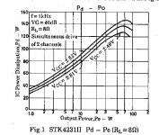
The STK device is limited by the max thermal dissipation of the package. Look at figure 1 in the data sheet. That shows a maximum output of only around 45 watts rms per channel at a supply of -/+53 volts. The -/+ 75 volt is an absolute electrical maximum that can be applied, but at that supply voltage the output would actually be lower because the IC would be running hotter.
For the powers you think you need, the only way is discrete.
http://www.diyaudio.com/forums/mult...much-voltage-power-do-your-speakers-need.html
The STK device is limited by the max thermal dissipation of the package. Look at figure 1 in the data sheet. That shows a maximum output of only around 45 watts rms per channel at a supply of -/+53 volts. The -/+ 75 volt is an absolute electrical maximum that can be applied, but at that supply voltage the output would actually be lower because the IC would be running hotter.
For the powers you think you need, the only way is discrete.
Attachments
Hi I have just built the amplifier from the schematic given on the datasheet of the STK4191V but I'm not sure if I'm using the right transformer. When I tested it the transformer heated up and melted the plastic coil former (I'm not sure if that's what it's called). The IC's heatsink heated up also. The transformer's secondary is rated at 3 Amperes. I saw on the datasheet of another STK IC which uses same recommended MG-200 equivalent transformer that the recommended bridge rectifier is rated at 4 Amperes. Should I use a 4 Ampere transformer too? Is that where the problem is? or are there any other possibilities of what went wrong? I just wanna add that I ommited the 3 microHenry coil which is connected in parallel to the 4.7 ohm resistor which connects to the load and what would be the effect? Noisier output perhaps?
yes, sure sign of insufficient transformer....your bobbin melted....
you can use a bigger traffo, one way to find out is the weight of the traffo that burned out, probably 2 to 3 times the weight is better...
that output coil isolates the output stage from highly capacitive loads at high frequencies, it is not advisable to remove them...
- Status
- This old topic is closed. If you want to reopen this topic, contact a moderator using the "Report Post" button.
- Home
- Amplifiers
- Chip Amps
- STK Choice