Hi everyone,
I got the mica installed today, and I discovered why the caps were blowing, there was a short from two of the pins of one of the LM chips to the ground.
Now I'm listening to it and have a question: When I first power up the amp, it sounds great, but after a few seconds (maybe 10), a distortion sets it, sounds like blown speakers. Is this related to the fact that it needs breaking in? I think it's getting better, but I'm not sure.
BTW, the mica didn't make that much of a difference. ie. it pretty much sounds the same with both chips on the heatsink that is not grounded, and with the mica and the grounding of the heatsink.
Thanks,
Jam
This is a general alert! 
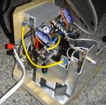
Hardwiring items together that are left 'floating' in the air will put massive strain on the joints and result in eventual failure. Alternatively leadouts will bend or sag causing a potential short circuit.
The GC amps lend themselves to hardwiring due to the small component count. This does not mean that they can be abused!
Hardwiring does not need to be a 'jungle'")
Hardwiring items together that are left 'floating' in the air will put massive strain on the joints and result in eventual failure. Alternatively leadouts will bend or sag causing a potential short circuit.
The GC amps lend themselves to hardwiring due to the small component count. This does not mean that they can be abused!
Hardwiring does not need to be a 'jungle'
An externally hosted image should be here but it was not working when we last tested it.
What do you mean by center tap? I added a ground from the bolt that goes right through the toroidal transformer, but that didn't do anything (there's no metal in the middle area). The transformer only has 2 AC leads and 4 DC outputs.
Please bear in mind that I'm just learning. This is a prototype and will not be used for anything. Hopefully if everything goes well I can use the experience and maybe the case.
I'm thinking I fried something when I had the short, and I should start with fresh parts again.
Thanks
Jam
Please bear in mind that I'm just learning. This is a prototype and will not be used for anything. Hopefully if everything goes well I can use the experience and maybe the case.
I'm thinking I fried something when I had the short, and I should start with fresh parts again.
Thanks
Jam
Well, I don't know if you've wired with one or two rectifier bridges.
If you've used two - i.e. one for positive rail and one for negative - make sure you've connected the - of the positive rectifier, the + of the negative rectifier, corresponding capacitors, ground and loudspeaker minus in one point: power star ground.
If you've used one rectifier, you will have joined two of the wires from the transformer. This is the center tap. Make sure this is connected with the middle point of the filter caps, ground and loudspeaker minus.
Rune
I've used two bridges. I'd like a bit more information before proceeding.
I've used one bridge per side: one for the right channel, one for the left channel. Are you saying to connect the - of both bridges to the ground? My ground is a star, and so far it has the following items attached (per channel):
+ All the metal parts, including the heatsink.
+ the - of the speakers
+ the - of the input
+ the - of the 1000 cap (its + goes to pin 1)
+ the + of the 1000 cap (its - goes to pin 4)
+ the - of the 22 uF cap
When we talk about one bridge or two, we mean per channel . So you have used one bridge in your circuit (just think of each channel separately to keep things simpler).
You should also have two ground stars, one for signal and the other for power. Take a look at my DD Gainclone pages as it is all explained there.
You should also have two ground stars, one for signal and the other for power. Take a look at my DD Gainclone pages as it is all explained there.
Near as I can tell from your description, you have one transformer winding feeding one rectifier bridge, and the start ground is not connected to the transformer at all. That's just not going to work very well, since there's nothing fixing the ground to half the supply voltage. For that you need a center tap on the transformer winding.
What you have now is not +-16.5 volts, it's just 33 volts.
You may be able to get by with something like two 470 ohm resistors across the 1000uF caps as a voltage divider, but it's hardly recommended.
Judging from the voltages you show in the first post, it might be best to connect - from one rectifier to + of the other, and use that point as ground. That'd give you +-33 volts, which would give you more power as well (provided your cooling is sufficient.)
Rune
I got it working!
Next, I'm building the real thing with Brian's boards and good parts.
Things that I did wrong in this project:
1. Short between one of the pins of the LM chip and the ground.
2. I may have wired the first caps wrong (Not sure about this).
3. Didn't use Mica to isolate the LM chips and the heat sink (the heat sinks were not connected to ground and didn't seem to matter).
4. I wired the bridges wrong ( I had used a single bridge per channel instead of combining them for the + and - power).
It sounds pretty good, considering the cheapo parts. I'll compare it with the good amp once it's built.
Thank you all for your help.
Jam
- Status
- This old topic is closed. If you want to reopen this topic, contact a moderator using the "Report Post" button.
- Home
- Amplifiers
- Chip Amps
- GC amp problem