I have seen references to National's PA100 design in threads before, but I still have questions, and I don't have enough knowledge to answer my questions.
Basically, based on what I've read in some threads, I am of the opinion that DC offset with multiple chips is a much bigger problem than you might think by browsing through National's AN-1192. I intend to use 0.1% resistors except for a 1% resistor on the output, but I suspect DC offset might still be an issue.
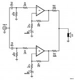
My question is about the caps in National's schematic, which I have highlighted with # and * symbols. Would using multiple Cin caps, 1 per chip, improve things, or could it be left out? Can the feedback cap Ci be deleted? What values for resistors or caps could be changed to reduce DC offset (other than the output resistor)?
Basically, based on what I've read in some threads, I am of the opinion that DC offset with multiple chips is a much bigger problem than you might think by browsing through National's AN-1192. I intend to use 0.1% resistors except for a 1% resistor on the output, but I suspect DC offset might still be an issue.
My question is about the caps in National's schematic, which I have highlighted with # and * symbols. Would using multiple Cin caps, 1 per chip, improve things, or could it be left out? Can the feedback cap Ci be deleted? What values for resistors or caps could be changed to reduce DC offset (other than the output resistor)?
Attachments
beaf up PA-100
Leadberry
You are right about the DC-offset issue when paralleling chips.
To answer your questions first.
No, multiple Cin caps will not improve the DC-offset and would be a waiste of money. It is there to prevent DC from your source/preamp getting to the chips/output. If your are 100 % sure that there is no DC comming form your source/preamp you can leave it out.
No, don't leave out the 68 uF feedback cap. This makes sure that you only have unity gain at DC. (x1).
You could make the feedback resistors (20K/1K) lower to get lower DC-offset, but then you would had to make the feedback capacitor bigger. This approach opens up a lot of other stuff, so I think you should leave that for now.
It is not as difficult as it may seems to get the parallingen going. There are 3 major issues to look out for:
A. Make sure the to chips don't sink/source each others DC-offset. This can be done by eacher lower the DC-offset as much as possible and/or making the output resistor bigger. Both solutions has its ups and downs.")
B. Make sure the gain is the same for both chips so they share the load equal. In your case 1K & 20 K. Using 0.1% is fine.
C. Make sure that the output resistor is as eaqual as possible also to make sure that they share the load.
If you use normal 1% resistor for B. & C. it will moste likely work for 98 % of the time. (1% resistors comming form the same batch are 0.3-0.5 %)
However you MUST deal with the DC-offset in a propper manner.
Remember that if you have an DC-offset at one amp of +12 mV and the ohter amp at say -14 mV and your output resistors are 0.1 R you have 130mA going from one amp to the other (26mV/0.2ohm)
Adding more chips in parallel just make it even more "fun" regarding the current flowing.
Have fun
THomas
Leadberry
You are right about the DC-offset issue when paralleling chips.
To answer your questions first.
No, multiple Cin caps will not improve the DC-offset and would be a waiste of money. It is there to prevent DC from your source/preamp getting to the chips/output. If your are 100 % sure that there is no DC comming form your source/preamp you can leave it out.
No, don't leave out the 68 uF feedback cap. This makes sure that you only have unity gain at DC. (x1).
You could make the feedback resistors (20K/1K) lower to get lower DC-offset, but then you would had to make the feedback capacitor bigger. This approach opens up a lot of other stuff, so I think you should leave that for now.
It is not as difficult as it may seems to get the parallingen going. There are 3 major issues to look out for:
A. Make sure the to chips don't sink/source each others DC-offset. This can be done by eacher lower the DC-offset as much as possible and/or making the output resistor bigger. Both solutions has its ups and downs.
B. Make sure the gain is the same for both chips so they share the load equal. In your case 1K & 20 K. Using 0.1% is fine.
C. Make sure that the output resistor is as eaqual as possible also to make sure that they share the load.
If you use normal 1% resistor for B. & C. it will moste likely work for 98 % of the time. (1% resistors comming form the same batch are 0.3-0.5 %)
However you MUST deal with the DC-offset in a propper manner.
Remember that if you have an DC-offset at one amp of +12 mV and the ohter amp at say -14 mV and your output resistors are 0.1 R you have 130mA going from one amp to the other (26mV/0.2ohm)
Adding more chips in parallel just make it even more "fun" regarding the current flowing.
Have fun
THomas
Thanks for your detailed reply!
So you are saying the following modification wouldn't improve DC offset? I was under the impression from comments in another thread that it would be better since now a slightly different bias current for each chip would result.
(BTW, I know the input impedance has now changed, not an issue to me.)
So you are saying the following modification wouldn't improve DC offset? I was under the impression from comments in another thread that it would be better since now a slightly different bias current for each chip would result.
(BTW, I know the input impedance has now changed, not an issue to me.)
Attachments
One other thing you could do witht he second scematic to help a bit further would eb to match the impedances to the two input pins more closely. You could do this by changing Rf to a 47k resistor and Ri to a 2.2k one which would give aproximately the same gain as before but with better impedance matching on the inputs.
bigparsnip said:One other thing you could do witht he second scematic to help a bit further would eb to match the impedances to the two input pins more closely. You could do this by changing Rf to a 47k resistor and Ri to a 2.2k one which would give aproximately the same gain as before but with better impedance matching on the inputs.

I already ordered the 0.1% resistors, they are 898 ohms and 21 Kohms! What should I make the other resistors?
well, you could change the vaues of Rin to the same as the Rf resitors (I doubt these will need to be 0.1% tollerance, 1% metal films should do fine). The only problem with this is it will lower the input impedance of your amp to around 1ok ohms (which should be ok, but if your pre amp isn't up to much you may have botther driving it.
- Status
- This old topic is closed. If you want to reopen this topic, contact a moderator using the "Report Post" button.