Hello there, as the title suggests what could be done in order to make sure the signal input pin voltage limit is not reached? The datasheet states that +/-0.4v is the max that can appear on this pin which doesn't seem like much at all.
I currently have a volume control potentiometer after the DC blocking capacitor to vary the audio signal from my laptops headphone jack but the signal could easily exceed .4v if the volume on the laptop is turned up enough.
Would two diodes in anti-parallel on the input pin work as a voltage clamp or will that cause other problems? Are there any better ways of doing it?
Thanks.
Attachments
What is the chip ?
LM386 but it applies to any chip amp I guess.
The LM386 is an odd one out tbh because although it is single rail, it has ground referenced inputs.
In practice its not a problem because the gain is high and so if you overdrive it then it will just clip and distort.
The 0.4 volt limit would apply if you were connecting a source that could supply lots of current. For example connecting a 1.5 volt battery to the input would not be a good idea, whereas a 1.5 volt battery via a 10k wouldn't do any harm.
Its the current flow into the input pin that is the killer, the voltage at which that current may start to flow is somewhere over 0.4 volts.
So as a headphone amp fed from a line output there is no problem.
Diodes are a bit marginal for protection because they are on the cusp of conducting at 400mv and that could cause distortion on transient peaks.
The LM386 is an odd one out tbh because although it is single rail, it has ground referenced inputs.
In practice its not a problem because the gain is high and so if you overdrive it then it will just clip and distort.
The 0.4 volt limit would apply if you were connecting a source that could supply lots of current. For example connecting a 1.5 volt battery to the input would not be a good idea, whereas a 1.5 volt battery via a 10k wouldn't do any harm.
Its the current flow into the input pin that is the killer, the voltage at which that current may start to flow is somewhere over 0.4 volts.
So as a headphone amp fed from a line output there is no problem.
Diodes are a bit marginal for protection because they are on the cusp of conducting at 400mv and that could cause distortion on transient peaks.
Well there will be a minimum of 2k in series with any audio source to the input pin since I have a stereo to mono mixer at the input + RC low pass filter to stop radio signals from getting in, but the 10k pot can be dialed to 0 ohms.
I just checked on the scope and I can easily make the input pin voltage exceed 0.4v, but this will not be a problem with the 2k minimum resistance in series? I have the gain set to 20 to reduce hiss plus my audio sources are designed to drive headphones so they can supply a good voltage swing at a decent amount of current if needed.
Will that be a problem for the input pin?
Thanks again, I did read this What are all those parts for which shows the diodes at the input of the chip but didn't know if that applies to my situation.
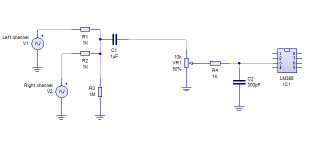
I've drawn up a simplified version of my input stage, there are some ferrite beads in there too and the RC filter is right at the input pin because I live next to a local radio transmitter that gets received by everything including the 6cm PCB track between input pin and volume pot.

The LM386 is an odd one out tbh because although it is single rail, it has ground referenced inputs.
.
Wouldn't that be true for all single rail chip amps for example TDA2822m?
Attachments
Last edited:
There won't be a problem beyond overdriving (clipping). Running on a 9 volt single rail and with a gain of 20 means that an input voltage of -/+200 millivolts will deliver -/+ 4 volts at the output. Anything beyond that will distort and clip. So there is no problem. In practice you may need an attenuator at the input in order to get a useful range of the volume control.
For a normal opamp (as in your link) the two inputs always see the same voltage (so no differential between them) and the two diodes would normally not do anything.
I'd have to look up the TDA2822 but I suspect it will be similar to the LM386 as regards biasing.
For a normal opamp (as in your link) the two inputs always see the same voltage (so no differential between them) and the two diodes would normally not do anything.
I'd have to look up the TDA2822 but I suspect it will be similar to the LM386 as regards biasing.
There won't be a problem beyond overdriving (clipping). Running on a 9 volt single rail and with a gain of 20 means that an input voltage of -/+200 millivolts will deliver -/+ 4 volts at the output. Anything beyond that will distort and clip. So there is no problem. In practice you may need an attenuator at the input in order to get a useful range of the volume control.
For a normal opamp (as in your link) the two inputs always see the same voltage (so no differential between them) and the two diodes would normally not do anything.
I'd have to look up the TDA2822 but I suspect it will be similar to the LM386 as regards biasing.
I managed to measure around 1000mW of output power before clipping when using 12v into 8 ohm, the poor LM386 got a bit hot though
 I guess its down to the low ESR output coupling capacitor I used, every little helps with these old low power chip amps.
Isn't the volume control pot the same as an attenuator?
Yes, the volume control is an attenuator but with a high gain amplifier fed from an already high signal source then you might find you need to cut the overall signal down before the volume control, otherwise you may only be using the first few degrees of rotation of the control before it all gets to loud and distorted.
Yes, the volume control is an attenuator but with a high gain amplifier fed from an already high signal source then you might find you need to cut the overall signal down before the volume control, otherwise you may only be using the first few degrees of rotation of the control before it all gets to loud and distorted.
Ah I get you now, so perhaps another potential divider before the volume pot?
Right now its kind of inadvertently matched up with my phones headphone jack in that clipping will occur just as they are both dialed to the max.
I've also made one of these clipping indicators https://www.instructables.com/id/Clip-Indicator-LED-for-any-power-amp/ as I know that clipping can really mess up a speaker (I've had voice coils start rubbing in the past). Its basic but seems to be good enough.
I doubt you would get enough current from an LM386 to damage a speaker but its useful to know when clipping does occur.
The important thing with the volume control and any attenuator is simply to get the feel of the volume control correct. Its something you can only judge by trial and error.
The important thing with the volume control and any attenuator is simply to get the feel of the volume control correct. Its something you can only judge by trial and error.
I'm not sure what the LM386 input voltage spec is supposed to mean.
The real "danger" is, as Mooly says, the current. This limit is, sadly, not specified. However essentially all pins on old-type designs will take 10mA. (Side-effect of ESD protection, if nothing else.) Looking only at your 1K, you can put 10V at it and it will not blow-up.
Further study shows the input is Darlington diff-pair. In conventional process it won't break-down to 14V either way. Two 7V B-E breakdowns. In fact the '386 inputs are lateral PNP which have even higher breakdowns (possibly the 12V-20V of the base process). However at -0.6V the input B-C junction forward-biases as a simple diode to ground.
Experience says that LM386 do not die easily.
If one does, it is a 59 cent repair.
- Status
- This old topic is closed. If you want to reopen this topic, contact a moderator using the "Report Post" button.
- Home
- Amplifiers
- Chip Amps
- Signal input pin overvoltage protection