I have most of stuff on hand, and want to have a small intergearted amp (for my 4x5m room). Being a newbie with very little electronic knowledge, it' better to seek for comments from experts here.
Note:
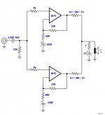
- LM3875TF x 2 per channel ( parallel ), no servo
- Power +/- 35V dc 250 VA per channel
- Cap 2x 1,000UF /per chip
- All R 1/4W 1% except Rout 0.1Ohm 3W 5%
1). Will this design work, particularly for 88dB speakers?
2). Is the input impedence is too low (output from CD go directly to the Amp via 50K pot).
3) More ideas for improvement are always welcome.")
Many thankssss in advance!
Note:
- LM3875TF x 2 per channel ( parallel ), no servo
- Power +/- 35V dc 250 VA per channel
- Cap 2x 1,000UF /per chip
- All R 1/4W 1% except Rout 0.1Ohm 3W 5%
1). Will this design work, particularly for 88dB speakers?
2). Is the input impedence is too low (output from CD go directly to the Amp via 50K pot).
3) More ideas for improvement are always welcome.
Many thankssss in advance!
Attachments
No.
Read this link to understand theory/issues:
http://www.diyaudio.com/forums/showthread.php?s=&threadid=11133
Read this link to understand theory/issues:
http://www.diyaudio.com/forums/showthread.php?s=&threadid=11133
1) Yes it will. You should be able to get around 110 W into 4 ohms according to the Overture Design Guide spreadsheet. As always, YMMV.
2) The input impedance should be OK.
The only suggestion that I would make is to use a zobel network per chip, before the 0.1 ohm output resistor, rather than just one zobel after the resistors.
When constructing, do not connect the outputs (do not install the 0.1 resistors) until you have done some basic but important testing. You are basically connecting the outputs of two amps together with nothing but 0.2 ohms between them. If something goes wrong, it will go wrong in a most spectacular way.
Each amp should function perfectly on it's own, with no oscillations, no excessive heat, and no other signs of trouble. You should measure the offset voltage of each amp, and ensure that it is not too different. Remember that the difference in voltage here will create a current flowing from one amp to the other through just 0.2 ohms of resisitance! Also measure the AC output of each amp with a steady test tone. It should be very close to the same. If it is too different, then the gain of one amp is higher than the other. This also creates a current from one amp to the other which will cause extra wasted heat and unnecessary drain on your power supply. Find matched pairs of gain setting resistors using an ohmeter to ensure that the gains are equal.
loong said:I have most of stuff on hand, and want to have a small intergearted amp (for my 4x5m room). Being a newbie with very little electronic knowledge, it' better to seek for comments from experts here.
Note:
- LM3875TF x 2 per channel ( parallel ), no servo
- Power +/- 35V dc 250 VA per channel
- Cap 2x 1,000UF /per chip
- All R 1/4W 1% except Rout 0.1Ohm 3W 5%
1). Will this design work, particularly for 88dB speakers?
2). Is the input impedence is too low (output from CD go directly to the Amp via 50K pot).
3) More ideas for improvement are always welcome.
Many thankssss in advance!
I'd say if this is your first project why use 2xLM3875? For 88dBm speakers and the room you specified single IC LM3875 should be just fine for 6-8 Ohm speakers.
I'd keep it simple as a first attempt. You may find you don't need more any way.
/Greg
Did you not read my comment or do you just enjoy disagreeing with others? I said...I disagree with macboy. At the very least, you need 0.1% tolerance resistors setting the gain to make sure each chip is sharing the load.
We do not need to use high precision resistors because we are not mass-manufacturing this thing. Hand matching will suffice quite well enough, and in fact can give better than 0.1% results.Find matched pairs of gain setting resistors using an ohmeter to ensure that the gains are equal.
Judging by the load in the schematic loong posted, I would assume that the speakers are 4 ohm. In that case, two parallel 3875's will perform much better than one.For 88dBm speakers and the room you specified single IC LM3875 should be just fine for 6-8 Ohm speakers.
macboy said:We do not need to use high precision resistors because we are not mass-manufacturing this thing. Hand matching will suffice quite well enough, and in fact can give better than 0.1% results.
Well then you had better describe the procedure to loong who described himself as a newbie on how to get better than 0.1% match with what probably is his 3-1/2 digit multimeter...
One thing that I would sujest which may be of some use here, is to use seperate input caps for each chip (rather than the single, common one currently being used). This will allow slightly diferent input bias curents to flow into each chip (which won't be identical) without creating a potential difference between the two. But, you would still need to use very close tolerance resistors to set teh feedback for the circuit.
Point taken. I made the assumption that he had access to a decent multimeter, but heh, you made the assumption that he had 0.1% resistors in his parts drawer... or at the local supply house. I think that more people have access to a 4.5 digit or better DMM than to .1% resistors. It doesn't matter though. We agree that the gain setting resistors must be very close in value so that the gains are equal and don't cause problems. That's really the point. Whether they are expensive high precision devices or just hand-matches cheapies is not.Well then you had better describe the procedure to loong who described himself as a newbie on how to get better than 0.1% match with what probably is his 3-1/2 digit multimeter
I might be able to find someone with hi-res multiter, but 0.1% Res is very difficult & too expensive.
As stated in the NS paper that '.. with 1% would give good result, but recommend 0.1%", so I don't think it will be serious/big concerns if I use 0.1% or 1% as long as it doesn't impact (noticable) the sound quality.
BTW,
Just confused if this one will work or not
As stated in the NS paper that '.. with 1% would give good result, but recommend 0.1%", so I don't think it will be serious/big concerns if I use 0.1% or 1% as long as it doesn't impact (noticable) the sound quality.
BTW,
Just confused if this one will work or not
loong:
I would not recommend using that circuit you posted. You'll likely have a DC offset at each output and an imbalance between the outputs. When the opamps fight, you lose.
The app note uses a unity gain opamp buffer and a 1k resistor before all the inputs to the 3875s. The reason for this is for the power opamps to have equal base impedances at their inputs. In the schematic you are showing, each opamp has 23k on the + input and only 680 on the - input. If you're intent on not using the buffer then the only way to keep the input impedance high and match +/- input impedances is to make the feedback resistors x10 (so 220k and 6.8k) and make your +input resistors 6.8k and remove the 22k input to gnd or similar values. Those seem like pretty high values though..
azira said:loong:
The app note uses a unity gain opamp buffer and a 1k resistor before all the inputs to the 3875s. The reason for this is for the power opamps to have equal base impedances at their inputs. In the schematic you are showing, each opamp has 23k on the + input and only 680 on the - input. If you're intent on not using the buffer then the only way to keep the input impedance high and match +/- input impedances is to make the feedback resistors x10 (so 220k and 6.8k) and make your +input resistors 6.8k and remove the 22k input to gnd or similar values. Those seem like pretty high values though..
You are almost right here, but if you look again you will see that teh lower feedback resistor is capacitively coupled to ground, so the bias curent will flow through the 22k feedback resistor from the output instead, so if you match the input impedance on the + input to this you will reduce the offset in a more conventional fassion.
bigparsnip said:
You are almost right here, but if you look again you will see that teh lower feedback resistor is capacitively coupled to ground, so the bias curent will flow through the 22k feedback resistor from the output instead, so if you match the input impedance on the + input to this you will reduce the offset in a more conventional fassion.
Hmmm... I think you're right. But he'll still need to change the Fb resistor to 23k or change the input resistor to 21k to match it up.
as long as the resistors don't need to be the exact value but need to be closed matched, why not just buy 2 resistors on tape, some stores sales them by 10 or so but they or still taped, this way you get an accuratie off way better then 1% but stil have the price off the 1% resistors. Witch aint mutch compared to 0.1% and 0.01% resistors
Rudy said:as long as the resistors don't need to be the exact value but need to be closed matched, why not just buy 2 resistors on tape, some stores sales them by 10 or so but they or still taped, this way you get an accuratie off way better then 1% but stil have the price off the 1% resistors. Witch aint mutch compared to 0.1% and 0.01% resistors
Because unlike transistors, resistors are tested and "binned" before they are cut into tapes. They only produce one line of resistors and then test them to see what their actual value is. The ones that ended up getting made within .1% of the target value are put into the same bin and the rest that are 1% of the target value are put together, then 2% then 5%. So what you actually end up getting when you get 5% resistors is a set of resistors that were more than +/- 2% away from the actual value. Bimodally distributed. The only set of devices that should have a normal distribution is the highest tolerance bin.
I measured some resistors on a tape, infact, many values on many tapes, and whilst the ones next to each other were often the same as measured by my cheap DMM, there is always a point (maybe after 2, 5, or 8 in a row) where they will measure different. So if my meter measures consistently, it shows just taking them off a tape does not gurantee they'll be the sameRudy said:maybe so, but have you actually tried it, i think not ...
(these were all 1% tol. metal film 1/4w)
- Status
- This old topic is closed. If you want to reopen this topic, contact a moderator using the "Report Post" button.
- Home
- Amplifiers
- Chip Amps
- Help! Parallel 2x 3875 per channel design - please advise.