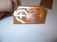
The problem, though, is the toner smears together and I have to make a touch up with an xacto knife on every part where thee toner smeared together, so, on this board, almost every trace connecting to the 3886.
Any ideas on how to fix this?
And what again was the stuff I should put on to get that greenish look and protect it?
-Mike
Any ideas on how to fix this?
And what again was the stuff I should put on to get that greenish look and protect it?
-Mike
An externally hosted image should be here but it was not working when we last tested it.
Those are 7mil tracks on a double sided board... this is how i do it.
I create the sch & pcb layouts in Protel.
I print the PCB layouts onto bubblejet transparency sheets using my Cannon bubblejet printer.
New bublejet printers using this special transparency sheeting (get from a printer supplies shop) can get quite amazing accuracy.
I tape the two sheets (both PCB sides) together so they are correctly lined up.
I then slide a piece of pre-sesitised PCB (i use Kingsten brand) between the sheets, and expose under a fluro desk lamp for 12mins each side (i flip the PCB over and expose one side at a time).
The rest you guys should know....
This procedure is quick, simple, cheap and i can get repeatable results.
Any questions?
")
soundNERD said:OK, I found a way that works pretty well with the kinkos paper i have.
heat the board for 2 minutes with it sitting on something hard (I use wood). An ironing board doesn't work.
place the paper where it will go, and it will stick to it.
iron for three minutes with pressure.
put in boiling water for 30 seconds.
peel off as much paper as possible
sand the rest off with VERY fine sandpaper.
etch
works so far. Some of the toner smeared, but i think that was because i printed at 1200x1200dpi, so there was too much ink on the paper. i have to try something like 300x300dpi or 600x600 dpi. but it was simply fixed with an exacto knife.
oops, forgot to say, its etching now, ill post some pics when it is done.
-Mike
Mike, guess no one is listening to you about only toner transfer. I agree though, I'm not going to try photo transfer and special boards.
But, I buy the PnP blue from All Electronics. It's $7.50 / 5 sheets if you buy 4 or more packs (presuming that you are going to make a few circuit boards over time. I'd suggest going with it better than super high gloss paper, it's about the same price. You can reuse the parts that weren't printed on for more boards if you only cut out what you use. I generally get atleast 2 to 4 boards done per sheet, but I can't make anything bigger than 3"x4" with the free Eagle.
I had to similar problems to overcome, first is that you need a very flat and hard surface to press against that won't absorb too much of the heat. I finally found that my tile kitchen counter works pretty good. I also found that when I used an iron that had a lot of steam holes on the bottom, there wasn't good pressure and contact. My new iron (which was the cheapest thing I could find) only has holes around the outside and works much better. However, my main problem is that my iron surface area is smaller than the board so I tend to have one area that is good but the part the other areas start to warp a little and don't transfer very well. If my boards were like 2" x 3" though, this would work really well.
My friend has some kind of special machine, like a converted laminator that he bought and says works really well. I'm thinking about trying it out, it's about $150.
--
Danny
thx everybody,
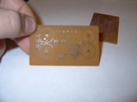
that paper i have still smears traces together, so I would like something that doesn't. Does that pnp stuff ever smear? can you do smd boards with it? I need to make some headphone amps with the sop version of the lm4881.
And here are the promised pics.
that paper i have still smears traces together, so I would like something that doesn't. Does that pnp stuff ever smear? can you do smd boards with it? I need to make some headphone amps with the sop version of the lm4881.
And here are the promised pics.
Attachments
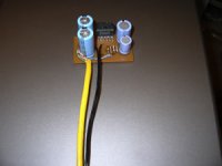
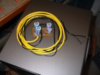

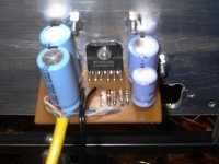
OK, I think this is the best amp I have ever designed. It looks great, and sounds great. I am a little disappointed with the bass responce though, except it could and most likelyt is I don't have enough filter caps (Only 1 2200uf on each rail). I am powering it with the torrid trafo from my old set of z680 speakers, so its definately getting enough amperage, even though it doesnt say on the trafo. And the trafo puts out +-26V so its getting enough voltage. It seems that it distorts easily when a base note hits, not even with the volume loud. Is this most likely because I don't have enough capacitance? Or since the wire is so long from the power supply, should I really have a 0.1uf cap on the chip?
When it's done, it is only going to have about 6 inches of wire. Finally, about the wire, was my desision to use cat5 good? I thought that the twisted pairs would be good for reducing line noise. But what I am not sure about is the input wire running along right next to the power wire.
Thx to all who can help,
Mike
Wiring considerations
Mike
Consider your input wires to be carrying low level signals. Consider your output to contain a high level signal. It is like putting an 800 lb gorrilla next to a spider monkey. Any transients along the high level line will likely be experienced by the low level line as noise. Seperate them. O shield them. Your use of twisted pair is good. Especially for the low level signal. The twist in wire effects a mutual cancellation along its path.
Continue having fun
Ed
maylar said:Very nice, MWP. What do you do for via's between top & bottom?
Single strands of wire.... annoying, but a good reason to keep the number of via's down to a minimum.
Most top to bottom connections i do using through-hole components, like resistors, caps, etc.
soundNERD said:thx everybody,
that paper i have still smears traces together, so I would like something that doesn't. Does that pnp stuff ever smear? can you do smd boards with it? I need to make some headphone amps with the sop version of the lm4881.
And here are the promised pics.
I've never had a smeared print out with pnp blue... but I have an HP Laserjet 4plus. I haven't done any SMD work yet. I have some SOIP OPA4134s that I might be putting to good use soon so maybe I'll find out one day how well it works. Dr Leach says that you can do traces up to .01 inches which I think should be enough.
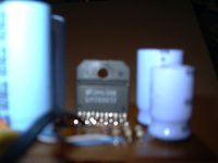
Does your digital camera have a button that looks like a flower? A lot of them have a macro-focus button that looks like a flower, it is used for when you need to focus on something closer than 2-ft... like a circuit board
--
Danny
Re: Wiring considerations
actually, it is input next to power supply voltages...
Any ideas on how to reduce distortion??? I wan't a little more volume before it distorts. I noticed that adding a second 2200uf cap to the ps (4400uf total per rail) helped a lot. Should I keep going and add another 2200 to each rail? I'm using the torrid trafo/rectifier from my replaced set of logitech z680s, so amperage/voltage is no issue. Its getting 26 volts, then the rectifier increases it. and its getting as many amps as needed to power a 500W amp system.
-Mike
bg40403 said:Mike
Consider your input wires to be carrying low level signals. Consider your output to contain a high level signal. It is like putting an 800 lb gorrilla next to a spider monkey.
Ed
actually, it is input next to power supply voltages...
Any ideas on how to reduce distortion??? I wan't a little more volume before it distorts. I noticed that adding a second 2200uf cap to the ps (4400uf total per rail) helped a lot. Should I keep going and add another 2200 to each rail? I'm using the torrid trafo/rectifier from my replaced set of logitech z680s, so amperage/voltage is no issue. Its getting 26 volts, then the rectifier increases it. and its getting as many amps as needed to power a 500W amp system.
-Mike
a link to a cheap proto house was posted on the ham radio newsgroup:
http://greatpcbdeals.easystorecreator.com/store.asp
$20
http://greatpcbdeals.easystorecreator.com/store.asp
$20
- Status
- This old topic is closed. If you want to reopen this topic, contact a moderator using the "Report Post" button.
- Home
- Amplifiers
- Chip Amps
- Making My Own PCBs