Hi Peterphuket,
Thanks for your valued views on my build.
After the numerous delays, my final beast will remain as it is.
Transparent labels? Maybe something to think of in the near future.
Listening pleasure has been is still is great, with many jealous neighbours!
Kay, please see post 613
Thanks for your valued views on my build.
After the numerous delays, my final beast will remain as it is.
Transparent labels? Maybe something to think of in the near future.
Listening pleasure has been is still is great, with many jealous neighbours!
Kay, please see post 613
Last edited:
Ha, ha, You're not so lucky, my next neighbour is 500 mtr from me.Hi Peterphuket,
Thanks for your valued views on my build.
After the numerous delays, my final beast will remain as it is.
Transparent labels? Maybe something to think of in the near future.
Listening pleasure has been is still is great, with many jealous neighbours!
Kay, please see post 613
Enjoy listening, like I do.
Kay, please see post 613
Yes, I have the German issue of this article handy, and there are still two complete Q-Watt kits in my shelves, waiting to become assembled.
Best regards!
I think I've been saying this yet: I've bought some rather cheap 24 V 5 A SMPS that I'll open and modify (remove the internal link from PE to the negative terminal, tweak for 27 V output voltage) and build a series connection of four of them per channel to get ± 54 Vdc.
Best regards!
Best regards!
i ordered 2 Q-Watt-Kits from elektor a week ago and started with populated the boards. I'm very curious after reading al the good reviews/experiences on diyaudio and elektormagazine.
I want use the Q-Watt-Amp in combination with the following preamp, i ordered these PCB's too:
Doug Self Preamp from Linear Audio #5
I want use the Q-Watt-Amp in combination with the following preamp, i ordered these PCB's too:
Doug Self Preamp from Linear Audio #5
Elektor Q-Watt & Preamplifier 2012
Preamplifier 2012 (1) - introduction and line-in/tone/volume board (110650) - Elektor LABS
A few more wiring connections left on my Elektor Preamp, but that's another forum thread (there are a few).
NE 5532 PreAmplifier from Doug Self, Elektor 2012
Preamplifier 2012 (1) - introduction and line-in/tone/volume board (110650) - Elektor LABS
A few more wiring connections left on my Elektor Preamp, but that's another forum thread (there are a few).
NE 5532 PreAmplifier from Doug Self, Elektor 2012
Preamplifier 2012 (1) - introduction and line-in/tone/volume board (110650) - Elektor LABS
A few more wiring connections left on my Elektor Preamp, but that's another forum thread (there are a few).
NE 5532 PreAmplifier from Doug Self, Elektor 2012
the Douglas Self preamp i'm mentioned is not based on the NE5532 but is based on the LM4562
John, how is your build going?
In the user 'Delange' and myself we used switched mode power supplies
Switched-mode Power Supply | Connex Electronic
In the user 'Delange' and myself we used switched mode power supplies
Switched-mode Power Supply | Connex Electronic
Input / Output lvs
A query plz.
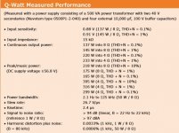
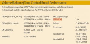
A query on the output level of the Preamplifier 2012 (Elektor April, May & June 2012) & input level on the Elektor Q-Watt Power Amp (Elektor September 2013).
As there appears to be quite a high level output from the Preamplifier 2012, if it's connected to the Q-Watt then there appears to be a 'mismatch' of levels.
Can something be done to keep them in line, otherwise i fear with the Preamplifiers volume turned up to a high level it could over-drive the Q-Watt.
A query on the output level of the Preamplifier 2012 (Elektor April, May & June 2012) & input level on the Elektor Q-Watt Power Amp (Elektor September 2013).
As there appears to be quite a high level output from the Preamplifier 2012, if it's connected to the Q-Watt then there appears to be a 'mismatch' of levels.
Can something be done to keep them in line, otherwise i fear with the Preamplifiers volume turned up to a high level it could over-drive the Q-Watt?
A query plz.
A query on the output level of the Preamplifier 2012 (Elektor April, May & June 2012) & input level on the Elektor Q-Watt Power Amp (Elektor September 2013).
As there appears to be quite a high level output from the Preamplifier 2012, if it's connected to the Q-Watt then there appears to be a 'mismatch' of levels.
Can something be done to keep them in line, otherwise i fear with the Preamplifiers volume turned up to a high level it could over-drive the Q-Watt.
A query on the output level of the Preamplifier 2012 (Elektor April, May & June 2012) & input level on the Elektor Q-Watt Power Amp (Elektor September 2013).
As there appears to be quite a high level output from the Preamplifier 2012, if it's connected to the Q-Watt then there appears to be a 'mismatch' of levels.
Can something be done to keep them in line, otherwise i fear with the Preamplifiers volume turned up to a high level it could over-drive the Q-Watt?
Attachments
As there appears to be quite a high level output from the Preamplifier 2012, if it's connected to the Q-Watt then there appears to be a 'mismatch' of levels.
Can something be done to keep them in line, otherwise i fear with the Preamplifiers volume turned up to a high level it could over-drive the Q-Watt?
I use a Tisbury Audio Mini Passive Preamp II.
Tisbury Audio - Mini Passive Preamplifier
Pops.
Last edited:
Can something be done to keep them in line, otherwise i fear with the Preamplifiers volume turned up to a high level it could over-drive the Q-Watt?
The easiest way is to use an attenuator between them.
Uneeda Audio - Build your own attenuator pads
Alternatively you could try and modify the gain of the preamp. I believe Douglas even commented on that in one of the two threads on his preamp (can't remember in which one it was but it was here on diyaudio).
Hi Calpe,
The problem is that you are using just a small part of the volume range to get say 0.1 to 1.0 Watts typically day to day, and then there is the risk that (normally sticky fingered children) someone cranks the dial up to 130 Watts at an inappropriate occasion.
The Tisbury unit deals with this with a handy dipswitch on the bottom which can switch in fixed attenuation. I have mine set to -20dB so peak output is about 5V at 100% and there is more useful range of control.
The only pity is that the fixed attenuation is not configurable per input channel. Maybe that's where the DIY comes in...
There are 20dB (or other) bullet attenuators available for RCA cables. Maybe that's a good option for you?
Pops.
I forgot to mention: the attenuator I use is 20 dB (I have built it inside my Q-Watt amplifier and can be disabled with a swtich). I have created a small (universal) PCB for that but you could just as easily build it on a small breadboard PCB. I use a PI-Pad type of attenuator.
Attachments
Thanks guys for your feedback.
Sticky fingers are my concern.
Having built the Elektor Preamplifer 2012, I don't really want to use (if I can help it) another unit.
Delange what you have sounds interesting, any chance of getting details, pcb....?
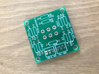
I made the small PCB to be universal so I can use it in different projects.
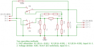
It basically features to functions: a PI-Pad attenuator or a voltage divider. In both cases there is a switch to allow for two positions. In this particular case the switch would select 0 dB or 20 dB attenuation. The schematic is attached.
For the 20 dB PI-Pad I used with my Q-Watt, I used following components:
R1A = 30k
R1B = 150 ohm
R2 = 5k
R3 = 240 ohms
Rout = 1M
The above resistors are metalic film 1%
The rest of the resistors are not populated.
The DTDP switch is mounted at the solder side of the PCB.
The input connector is wired as following:
IN-1: not connected
IN-2: signal input (connect to output of preamp)
IN-3: gnd
The output connector is wired as following:
OUT-1: signal output (goes to input of Q-Watt)
OUT-2: gnd
OUT-3: not connected
Attachments
Last edited:
- Home
- Amplifiers
- Chip Amps
- My Q-Watt project