The supplies are already done.
And hopefully the amplifier boards will also soon be ready.
Instead of using the standard connectors of the kit I purchased some pluggable ones.
Next I'll focus on the case. I'm planning to build them like I already did with my SymAsym.
An externally hosted image should be here but it was not working when we last tested it.
And hopefully the amplifier boards will also soon be ready.
Instead of using the standard connectors of the kit I purchased some pluggable ones.
An externally hosted image should be here but it was not working when we last tested it.
Next I'll focus on the case. I'm planning to build them like I already did with my SymAsym.
An externally hosted image should be here but it was not working when we last tested it.
I have attached how i built it.
For more details here's the original one.
I adjusted size and connectors. Hopefully I haven't made mistakes doing so.
For more details here's the original one.
I adjusted size and connectors. Hopefully I haven't made mistakes doing so.
Attachments
Does anybody know where I can get a PCB for the APEX regulated power supply without re - designing the PCB as many others have?
I have a trusty 625VA 35V transformer that might make a good AC source for a regulated 35-40V DC PS.
Pops.
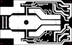
I've issued my design to the board house yesterday. My version does not include the large caps on the PCB (I don't trust that due to the weight of the caps). Instead, I use large off board caps with screws who connect to the PCB.
If you have a few weeks patience (probably 3 - 4 weeks) you can buy one or two boards from me. I don't know what the final price will be because customs are always a surprise...
The board measures about 65 x 124 mm and is intended to screw against the heatsink. The PCB includes fuses and bleeder resistors. The board has a fused and un fused output. I ordered 10 pcs since I will need a few more for other projects...
") I attached a sample in the PDF.
I attached a sample in the PDF.Attachments
If you have a few weeks patience (probably 3 - 4 weeks) you can buy one or two boards from me. I don't know what the final price will be because customs are always a surprise...
Hi Delange - yes please to two boards. I don't mind mounting the caps on a baseplate. You know I did the same for the 8x 10mF caps in my Q-Watt.
What is the maximum load current (RMS) for the board? I'm thinking about powering 4x 60W channels (Rod Elliott P3A).
What size heatsink? PCB does look good. Thanks.
Pops.
The max output current is 10A (with two pairs). Mister Mile designed it to power one SR-200. The output voltage can be adjusted from +/- 55 volts to +/- 90 volts. I noticed the P3A uses a +/- 35 volts supply; which is too low for the PSU-10.
Heatsink size, don't know. Mister Mile did not mention that but I suppose at near 10 A output, the transistors will get warm
Needs to be tested. Also note that the size of your transformer increases by using the regulated PSU. There needs to be a voltage drop of 10 to 15 volts over the supply for stability.
Shame... I really do need only 35V regulated. I don't have time/space/money/aluminium extrusions for a 200W amp
I expected to supply 10-15V higher DC hence the 35V AC tranny, gives 49V DC.
I would like to use each regulated PS to power one stereo P3A board, needs about 6A @ 35V DC. I'll ask Mile if the design can be easily adapted or not.
Pops.
I expected to supply 10-15V higher DC hence the 35V AC tranny, gives 49V DC.
I would like to use each regulated PS to power one stereo P3A board, needs about 6A @ 35V DC. I'll ask Mile if the design can be easily adapted or not.
Pops.
Last edited:
A voltage regulator compares the output voltage to the voltage reference.
It does not care about voltage input, nor voltage drop.
If you want 35Vdc as an output you select a voltage reference that gives this output.
Then select a transformer that when heavily loaded does not cause the regulator to drop out, even when mains voltage goes to lowest allowed within the supplier's tolerance.
But if you run 10A continuous output, then all heatsinks will run hot.
You don't design a ClassAB amplifier to operate with a continuous 10A supply.
The supply current varies from near zero milli-amps to peak output current into the speaker load.
But does the voltage drop (and load current) determine the power dissipated? A decent voltage drop is good for stability and >15V seems like excessive waste?A voltage regulator compares the output voltage to the voltage reference.
It does not care about voltage input, nor voltage drop.
Yep, got it.If you want 35Vdc as an output you select a voltage reference that gives this output.
Then select a transformer that when heavily loaded does not cause the regulator to drop out, even when mains voltage goes to lowest allowed within the supplier's tolerance..
But if you run 10A continuous output, then all heatsinks will run hot.
You don't design a ClassAB amplifier to operate with a continuous 10A supply.
The supply current varies from near zero milli-amps to peak output current into the speaker load.
Ok understood. The reason for 35V is to power 60W Class AB, chosen partly because peak current is lower. I want to use a smaller case/heatsink.
With a cheap Chinese mains power meter, I was able to measure some total idle power usage figures:
Q-watt amplifier uses approx 23 Watts total at idle (warm) and approx 24 Watts in normal (quiet) evening listening. Efficiency: schlecht, but better than Class A
Thats 1W total in bleeder resistors, 8W to each Q-Watt and 3W used in each side of the power supply (transformer core losses I expect).
Will repeat the test on my old 60W class D amp, which gets hot enough at idle to fry an egg....
Pops
Last edited:
With a cheap Chinese mains power meter, I was able to measure some total idle power usage figures:
Q-watt amplifier uses approx 23 Watts total at idle (warm) and approx 24 Watts in normal (quiet) evening listening. Efficiency: schlecht, but better than Class A
Thats 1W total in bleeder resistors, 8W to each Q-Watt and 3W used in each side of the power supply (transformer core losses I expect).
Will repeat the test on my old 60W class D amp, which gets hot enough at idle to fry an egg....
Pops
You now made me curious to know what my Q-Watts consume with an SMPS...
I ran the same meter on my old Rotel RA-971.
Rotel amp uses 16W after inrush (cold) then ramps up to 39.5W over approx 2 minutes.
Steady-state power usage at idle is 25W after 1 hour, when fully warmed up.
So the 120W Class AB amp uses less power at low levels than the 60W Class D amp. The heatsink inside the RA -971 is always very hot.
Pops.
Rotel amp uses 16W after inrush (cold) then ramps up to 39.5W over approx 2 minutes.
Steady-state power usage at idle is 25W after 1 hour, when fully warmed up.
So the 120W Class AB amp uses less power at low levels than the 60W Class D amp. The heatsink inside the RA -971 is always very hot.
Pops.
Measure it Delange. The Gearbest meter was less than £18 I think including delivery from China.You now made me curious to know what my Q-Watts consume with an SMPS...
Power Meter Measuring Outlet Socket UK PLUG-$14.1 Online Shopping| GearBest.com
Hi Delange & Popchops. So how's the Q-Watt's?
Been running mine everyday and it's music to the ears....
Let me know how you go with the fuse ratings
My Q-Watt's are running fine too.
I've had an issue with one of the SMPS's: one day one of the SMPS's just decided to stop working. The PS went into protection mode and the amp switched off. I placed the amp on my lab bench and opened the enclosure for some measurements. At power up the SMPS made a whistling sound and a few moments later the fuse of the SMPS blew up. Due to my experience with repairing SMPS's I knew I did not want to replace that fuse...
I contacted the vendor and they replaced the PS under warranty. It's up and running again since then.
My Q-Watt's see daily use; for listening to music and while watching TV. Very please with them.
- Home
- Amplifiers
- Chip Amps
- My Q-Watt project