Is it possible to use NJW3281G and NJW1302G instead of MG6330-R and MG9410-R for Q-Watt amplifier?
Nope, as Kay mentioned, you need more than one pair.
But Elektor still has kits which include all parts including the transistors.
There are still some source who have stock but the devices are EOL.
Nevertheless, it is a very nice amplifier and you won't be disappointed by its performance.
Hi, I've got a small question regarding using an regulated power supply. Since I need a transformer with a higher voltage output I'll surely have to adjust R19/R20 for the higher voltage.
Can I simply view R19/R20 as a voltage divider and higher R19 accordingly?
If so R19=34k for 50V AC input should be fine?
I'm a bit confused because I normally would only place R19 and ommit R20. And (at least german) intenet also tells me the voltage devider is a bad idea for a led.
Can I simply view R19/R20 as a voltage divider and higher R19 accordingly?
If so R19=34k for 50V AC input should be fine?
I'm a bit confused because I normally would only place R19 and ommit R20. And (at least german) intenet also tells me the voltage devider is a bad idea for a led.
Hi, I've got a small question regarding using an regulated power supply. Since I need a transformer with a higher voltage output I'll surely have to adjust R19/R20 for the higher voltage.
Can I simply view R19/R20 as a voltage divider and higher R19 accordingly?
If so R19=34k for 50V AC input should be fine?
I'm a bit confused because I normally would only place R19 and ommit R20. And (at least german) intenet also tells me the voltage devider is a bad idea for a led.
Elektor used a voltage devider to increase the off "speed". As soon as one of the secondaries loose power the LED in the opto-coupler goes off, disengaging the relays.
Using a higher supply voltage is less problematic for the opto-coupler circuitry than it is for the power amp stage. I believe +/- 60 volts is the max.
You could use Apexaudio's regulated power supply for the Q-Watt. The power supply can be adjusted to the required output voltage. See the thread on the "Studio Reference Amplifier". You'll need a bit of searching in there but the power supply is in that thread.
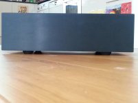
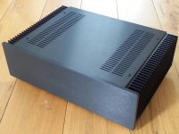
I found these AV mounts from RS, I prefer them to the HIFI2000 feet.
Available in 15kg (24mm high) or 10kg (20mm).
Pops.
Looking nice Pops.
I was looking for feet the other day (for my SR-200 amplifier project) and found some radicules prized feet. One German distributor wants to charge 75 Euro for 4 aluminium feet...
They are very nice and would be a great match to my Cambridge preamp but way too expensive!
Using a higher supply voltage is less problematic for the opto-coupler circuitry than it is for the power amp stage. I believe +/- 60 volts is the max.
You could use Apexaudio's regulated power supply for the Q-Watt. The power supply can be adjusted to the required output voltage. See the thread on the "Studio Reference Amplifier". You'll need a bit of searching in there but the power supply is in that thread.
Hey Delange I think Max said higher AC not higher DC. You might need 50V AC to supply 55V DC regulated. But the Q-Watt expects 40V AC. Pops.
Hey Delange I think Max said higher AC not higher DC. You might need 50V AC to supply 55V DC regulated. But the Q-Watt expects 40V AC. Pops.
Sure, but I wouldn't worry about a higher AC value. The opto-coupler LED is rated up to 50mA current. Even with an AC voltage of 50 or 55 volts, the opto-coupler drive current will still be well within the specs of the opto-coupler.
I already ordered a pair of 34k resistors, so I'll eventually solder them anyway. But it's good to know that even the original ones shouldn't cause any problems.
The apex-supply is exactly the one I am going to build. I've already sent some production files for the pcb to a manufacturer. I hope the pcbs will soon arrive.
But it's still a long way to go since I need to get an enclosure and some transformers.
The apex-supply is exactly the one I am going to build. I've already sent some production files for the pcb to a manufacturer. I hope the pcbs will soon arrive.
But it's still a long way to go since I need to get an enclosure and some transformers.
Hi Delange which PCB will you use for APEX SR200? DIY? If I do this again I would go for 4x 50W with electronic crossover. To power each speaker driver independently.
I don't know how good the SR50 is and it's obviously less popular.
Pops.
I have 10 PCB's designed by Alexmm version 3.2 on order. I ordered 10 to have an even number (min order is 5 pcs). I'm planning on selling a few of those PCB's at cost (plus shipping). They are on there way over here from China and I'll expect them to arrive within two weeks. The PCB's are for the SR-200, which have three output pairs.
I don't do DIY PCB's. To have them manufactured by a professional company is so cheap these days... you don't want to mess with all those toxic chemicals to build them yourself. Also, the quality from a professional board manufacture is way better than you own build PCB's.
I've also started designing a PCB for the AX14. Just for fun
")
I know there are designs in the "100W ultimate fidelity amplifier" but I want a more compact version (double sided PCB). That amp gets nice reviews too and it is rated 80 watts / 8 ohm.
I sometimes ask myself what I'm going to do with all those amps...
Last edited:
Hi Max - I'm very interested to see how this works out and also interested in spare PCBs for the APEX reg PS.The apex-supply is exactly the one I am going to build. I've already sent some production files for the pcb to a manufacturer. I hope the pcbs will soon arrive.
But it's still a long way to go since I need to get an enclosure and some transformers.
What will be the power dissipation from the Apex reg PS? Will you go for one or two transformers? With an audio quality regulator (40 kHz?) and ample capacitance I would have thought one large transformer is enough. The transformer is effectively isolated. Easier to get tighter regulation in one large transformer too.
I'm planning to use two transformers and two regulated supplies. Power dissipation should be about 50-60W per board at full load. At normal listening level it should be much smaller.
I'm sorry but I won't have spare PCBs. I only ordered two parts from a small company. If you want the PCB I can post it, it's basically this one rescaled to 100*160mm and fitted for use of four TO220 rectifiers.
I'm sorry but I won't have spare PCBs. I only ordered two parts from a small company. If you want the PCB I can post it, it's basically this one rescaled to 100*160mm and fitted for use of four TO220 rectifiers.
Yes pls Max. PCB files might be useful.
I used 2x 420VA transformers (41V AC off load) for the Q-Watt unregulated power supply, but with thick copper for tight regulation and extra turns for lower flux density.
Primary resistance 2.2R
Secondary resistance 0.2R, if I remember.
I would like to make the APEX regulated PS...
I used 2x 420VA transformers (41V AC off load) for the Q-Watt unregulated power supply, but with thick copper for tight regulation and extra turns for lower flux density.
Primary resistance 2.2R
Secondary resistance 0.2R, if I remember.
I would like to make the APEX regulated PS...
Attachments
Last edited:
I can send them to you on monday.
But be aware that I only have some picture files. Transferring them into the [quite old and windows xp only (backward compatibility from around 1980?!)] program I got from my father would have been more difficult for me than simply editing them with GIMP.
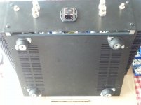
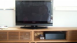
By now I have already bulit my Q-Watts and the power suplly PCBs.
I'm now building a turn on/softstart/filter circuit.(Hopefully with a proper program) I hope I'll be able to test all of it in late august.
My phone doesn't like uploading pictures as it seams so I'll do that tomorrow.
But be aware that I only have some picture files. Transferring them into the [quite old and windows xp only (backward compatibility from around 1980?!)] program I got from my father would have been more difficult for me than simply editing them with GIMP.
By now I have already bulit my Q-Watts and the power suplly PCBs.
I'm now building a turn on/softstart/filter circuit.(Hopefully with a proper program) I hope I'll be able to test all of it in late august.
My phone doesn't like uploading pictures as it seams so I'll do that tomorrow.
- Home
- Amplifiers
- Chip Amps
- My Q-Watt project