The Q-Watt amplifier from Elector caught my attention a long time ago. The project caught my attention due to its simplicity but yet interesting specifications. I finally bought the two kits a few months ago and I started building it this week.
Since I couldn’t find many posts about this amplifier I decided to post the progress of my project here. My project consists of two mono block amplifiers who will be placed right behind the speakers. The idea is to make them as invisible as possible. The project has been growing inside my head since a couple of months (and some parts are still growing). The enclosure was one of the points of attention. I couldn’t find anything on the marked so I decided to design and build the enclosure myself.
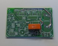
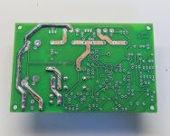
The first thing I did was to solder a 1.5mm2 wire across the pcb traces who need to carry a lot of power. I’m a bit skeptic about thickness of those traces… So this is what I did:
<see image 1>
<see image 2>
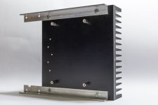
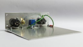
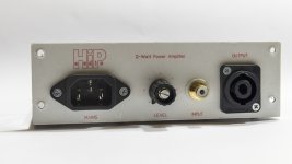
I left the electronics part rest for a while and started with some of the mechanical build of the enclosure. The back plane consists of an aluminum L profile of 50 x 20 x 2. It has the same with as the SK85 heat sink I’ll be using (160 mm). The back plane holds all the in- and outputs: mains, level adjust, input and speaker output connectors. I made the “front panel” myself and printed it on a label. After applying the label to the back plane I used a clear adhesive foil on top of the label. This must protect the label.
<see image 3>
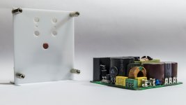
The base plate is attached to the back plane by four screws. I used an aluminum plate of 160 x 150 x 2 mm. This will be the footprint of the enclosure.
<see image 4>
I’ll be using a SMPS for this project. Initially I planned on using a traditional transformer but the size and weight made me change my mind. I ended up buying two SMPS500R power supplies with 2 x 55 volts. These are 500 watts power supplies and they get very good reviews. The SMPS’s are smaller, lighter, cheaper and should provide better performance than a traditional transformer based power supply. I’m curious about how they will perform. The SMPS’s will be mounted inside the enclosure by this mount:
<see image 5>
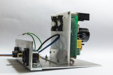
The back side of the enclosure is largely made up of the heat sink. The amplifier PCB will be fixed flat against the heat sink in order to save space. There are two aluminum L profiles of 10 x 10 x 2 to fix the heat sink to the back plane. The PCB will be screwed on 4 metal standoffs of 10 mm:
<see image 6>
The mechanic construction is progressing well. Here is how the power supply is fitted in the enclosure:
<see image 7>
Before fixing the heat sing to the back plane I’ll be installing the amplifier’s PCB and transistors. Next on the ‘to do’ list is to populate the PCB, do the adjustments and finally install the heat sink to the back plane. I’ll probably do that tomorrow. To be continued…
Since I couldn’t find many posts about this amplifier I decided to post the progress of my project here. My project consists of two mono block amplifiers who will be placed right behind the speakers. The idea is to make them as invisible as possible. The project has been growing inside my head since a couple of months (and some parts are still growing). The enclosure was one of the points of attention. I couldn’t find anything on the marked so I decided to design and build the enclosure myself.
The first thing I did was to solder a 1.5mm2 wire across the pcb traces who need to carry a lot of power. I’m a bit skeptic about thickness of those traces… So this is what I did:
<see image 1>
<see image 2>
I left the electronics part rest for a while and started with some of the mechanical build of the enclosure. The back plane consists of an aluminum L profile of 50 x 20 x 2. It has the same with as the SK85 heat sink I’ll be using (160 mm). The back plane holds all the in- and outputs: mains, level adjust, input and speaker output connectors. I made the “front panel” myself and printed it on a label. After applying the label to the back plane I used a clear adhesive foil on top of the label. This must protect the label.
<see image 3>
The base plate is attached to the back plane by four screws. I used an aluminum plate of 160 x 150 x 2 mm. This will be the footprint of the enclosure.
<see image 4>
I’ll be using a SMPS for this project. Initially I planned on using a traditional transformer but the size and weight made me change my mind. I ended up buying two SMPS500R power supplies with 2 x 55 volts. These are 500 watts power supplies and they get very good reviews. The SMPS’s are smaller, lighter, cheaper and should provide better performance than a traditional transformer based power supply. I’m curious about how they will perform. The SMPS’s will be mounted inside the enclosure by this mount:
<see image 5>
The back side of the enclosure is largely made up of the heat sink. The amplifier PCB will be fixed flat against the heat sink in order to save space. There are two aluminum L profiles of 10 x 10 x 2 to fix the heat sink to the back plane. The PCB will be screwed on 4 metal standoffs of 10 mm:
<see image 6>
The mechanic construction is progressing well. Here is how the power supply is fitted in the enclosure:
<see image 7>
Before fixing the heat sing to the back plane I’ll be installing the amplifier’s PCB and transistors. Next on the ‘to do’ list is to populate the PCB, do the adjustments and finally install the heat sink to the back plane. I’ll probably do that tomorrow. To be continued…
Attachments
Could you attach a hand drawn schematic of what you have built?
Andrew, I'm building the Q-Watt amplifier from Elektor.
Follow the above link if you want schematics, PCB files, documentation and so on. (You might need to create an account on the Elektor website to be able to download anything).
It would be much more convenient for us Members to see everything here on the Forum.
What about attaching details here?
I attached the schematics and the PCB files.
Since I used a different heat sink (SK85), I have also attached my own drilling template.
Attachments
Hi delange!
I followed you from the Q-Watt forum. I'm using a bog-standard 3U 300mm deep case from hifi2000. Ordered today :-D
I see you are using a beefy speaker output connector. Is that a Speakon? Can anybody advise on output connector options for 200W system? Is there anything wrong with binding posts?
I followed you from the Q-Watt forum. I'm using a bog-standard 3U 300mm deep case from hifi2000. Ordered today :-D
I see you are using a beefy speaker output connector. Is that a Speakon? Can anybody advise on output connector options for 200W system? Is there anything wrong with binding posts?
Hi delange!
I followed you from the Q-Watt forum. I'm using a bog-standard 3U 300mm deep case from hifi2000. Ordered today :-D
Hi there, looking forward seeing your project!
I see you are using a beefy speaker output connector. Is that a Speakon? Can anybody advise on output connector options for 200W system? Is there anything wrong with binding posts?
That is indeed a speakon.
Binding posts are okay but there more prone to short cutting your amp.
I like speakon because it can handle huge currents and it is a compact housing.
Hello,
I also follow your project through the Q-watt forum, and an already at an advanced stage to build it.
But I have a question concerning the power supply. on connector K7 you'll need 2 times 40V AC, from where you'll apply that?
As somebody mention on the same forum I'll apply klixons on the heatsink to switch of the mains at 75 degree celsius.
Hi guys.
I cannot believe the main heatsinks (300x120x40mm in my case) will ever get to 75 deg C. At 0.5 deg/W that's about 90W waste heat!
I like the idea of Speakon connectors but I also need some way to connect my high-impedance active sub to both left and right channels. At present on my old Rotel amp, I have wound these 4 wires (left signal+ground, right signal+ground) around the speaker binding posts on the amp. The sub side of this cable has a 4-way Speakon interface.
If I switch to Speakons out of my new amp then I need another (third) speaker output (4-way) for the sub. Has anybody done this? Am I barking up the wrong tree?
But I have a question concerning the power supply. on connector K7 you'll need 2 times 40V AC, from where you'll apply that?
The SMPS500R has an aux output. In my case (dual 55 volts PS), there is a dual 16 volts aux output. I'll use the +16 volts to power the LED of the 4N25.
To do that, I don't use R20, D3, D4 and C14 on the Q-Watt PCB. R19 will be 1k5 ohms and D3 will be replaced by a wire. I then connect the 16 volts of the aux output to K7 (first and second position; third position is unused).
Hi guys.
I cannot believe the main heatsinks (300x120x40mm in my case) will ever get to 75 deg C. At 0.5 deg/W that's about 90W waste heat!
I like the idea of Speakon connectors but I also need some way to connect my high-impedance active sub to both left and right channels. At present on my old Rotel amp, I have wound these 4 wires (left signal+ground, right signal+ground) around the speaker binding posts on the amp. The sub side of this cable has a 4-way Speakon interface.
If I switch to Speakons out of my new amp then I need another (third) speaker output (4-way) for the sub. Has anybody done this? Am I barking up the wrong tree?
You could use 4 way Speakons on your Q-Watt amplifier. This way, each Speakon can have left and right (+ and - 1 for left channel; + and - 2 for right channel).
You will need to make your own speaker cables:
* "left" speaker speakon: use + and - 1 for main speakers. Use + and - 2 for right channel sub.
* "right" speaker speakon: use + and - 2 for main speaker. Use + and - 1 for left channel sub.
40V AC is intented to come direct from a transformer before rectification to 55V.
The purpose is to switch off the speaker relais immediately after power has been switched off. By using the aux output of the SMPS I do the same.
@Popchops,Hi guys.
I cannot believe the main heatsinks (300x120x40mm in my case) will ever get to 75 deg C. At 0.5 deg/W that's about 90W waste heat!
I like the idea of Speakon connectors but I also need some way to connect my high-impedance active sub to both left and right channels. At present on my old Rotel amp, I have wound these 4 wires (left signal+ground, right signal+ground) around the speaker binding posts on the amp. The sub side of this cable has a 4-way Speakon interface.
If I switch to Speakons out of my new amp then I need another (third) speaker output (4-way) for the sub. Has anybody done this? Am I barking up the wrong tree?
It depending where you lives, like me in the far east with an average temperature between 30 and 40 degrees Celsius, it is not so special.
Queries
Hiya,
I too have been following the project on Elektor Labs.
I'm interested to have some views/feedback on cases to fit two Q-Watt boards and two SMPS's inside one case.
Apart from that having ordered the recommended heatsinks, i assume they have to be mounted so that the 'fins' point out, rather than lay the heatsink flat with the 'fins' pointing downwards?
I've included a Spares list that should help constructors (sorry its pdf).
Cheers
Attachments
To be fully effective the gaps between the fins must pass cooling air.
This requires that the fins be vertical so that the partially warmed air in contact with the fins can rise up through the gaps. The gaps act like chimneys.
It was probably shown to you in science classes at early school.
This requires that the fins be vertical so that the partially warmed air in contact with the fins can rise up through the gaps. The gaps act like chimneys.
It was probably shown to you in science classes at early school.
- Home
- Amplifiers
- Chip Amps
- My Q-Watt project