Hi everyone:
Newbie to electronics here, with little to no knowledge of the subject-just able to solder and follow instructions.
I've been slowly assembling 2 pairs of Chipamp.com LM3886 dual mono kits. I'm almost finished, but have a problem with the last PSU. All the PSUs were built stock, by the way.
The last PSU tests fine on a DMM's DCV setting. Hower, it seems to show strange behaviour on the scope (but test right on a DMM for DCV). After having mastered my soldering technique a while back, I'm fairly sure it's not a solder joint problem.
Channel 1 = Neg. side of supply
Channel 2 = Pos. side of supply
Channel 1 is displaying a voltage on the scope of 10.4 - 11.0mV.
Channel 2 is displaying between 40 - 60mV.
The weirdest thing is, unless I use Autoset, I can't manually adjust voltage and time controls to obtain the trace for Channel 2 (pos. side). And if I get the trace, and I adjust voltage or time, the trace disappears even if I go back to the same voltage and trace settings a few seconds later.
See below.
Can anyone suggest what might be wrong with the board or the setup?
Last edited:
A bit confusing as to what you are trying to do...
1/ Is the DC voltage of each rail correct as measured on a DVM ?
2/ Use one channel of the scope (use AC coupling) and measure the ripple on each rail in turn. If the ripple is a little different between rails then that could be because any DC current draw from the rails is slightly different.
1/ Is the DC voltage of each rail correct as measured on a DVM ?
2/ Use one channel of the scope (use AC coupling) and measure the ripple on each rail in turn. If the ripple is a little different between rails then that could be because any DC current draw from the rails is slightly different.

Blast it! Why can't I get the dang images to display?! I have this problem every time I try to post images here. Is something buggy?
Pos. side of supply measures 26.71V
Neg. side of suppply measures 26.72V
So yeah, close enough, right?
EDIT: Apologies Mooly. I was trying another post to try to get
images posted. I deleted the dupe and thank you.
Pos. side of supply measures 26.71V
Neg. side of suppply measures 26.72V
So yeah, close enough, right?
EDIT: Apologies Mooly. I was trying another post to try to get
images posted. I deleted the dupe and thank you.
To add a photo, files or non standard files.
First click "go advanced" in the box below the "quick reply" message box. Doesn't matter if you decide half way through a message to do that, it carries it forward.
Then click "Manage attachments". Maximise the new Window so that you can see all the text.
Click browse in the first box at the top and find your picture. Repeat for any more pictures.
Click upload... a message appears "uploading"
When complete the files will show as being attached. Now click the small text that says "close this window"
The pictures should now be attached and when you submit your post they will appear.
Make sure your pics aren't too big, a couple of 100k is plenty, and many members object when they are massive and it alters the margins
It tells you in the attachments window what max sizes are allowed.
If you want to attach a file that has a non standard format for example excel, circuit simulation etc then try putting the files in a zipped folder and attaching that.
Pos. side of supply measures 26.71V
Neg. side of suppply measures 26.72V
So yeah, close enough, right?
Those sound fine. Now use just one channel of the scope (initially at least) to measure and record the ripple present. Then you can try and figure how to set the scope in dual trace mode to display both together... but you will need AC coupling for both channels if you want to view a small ripple component, otherwise the DC voltage will drive the trace off screen.
Hmmm...I was using "Insert image". What the heck is insert image for, if not for, you know...inserting images..<ugh> Thanks Mooly.
View attachment DS0035.BMP
Do I maybe have something set wrong with my scope, cause Channel 1 is supposed to be a -Ve voltage, and it's showing a pos. voltage (the number appears correct).
View attachment DS0035.BMP
Do I maybe have something set wrong with my scope, cause Channel 1 is supposed to be a -Ve voltage, and it's showing a pos. voltage (the number appears correct).
Last edited:
Hard to know whats going on without being there and being familiar with the scope. Begin with Channel 1 only and firstly zero the trace on the centre line. Then if you connect it to the PSU positive rail you should see the trace deflect upward by the DC voltage (for DC coupling of Channel 1 input), and if you then switch to AC coupling and turn the volts/div sensitivity 'up' (so lower value of volts/div) you should see the AC ripple.
Keeping everything set the same transfer the probe to the other rail and you should see a mirror image, the trace deflecting downward for showing the DC volts.
(Is there an 'invert' setting for the scope channels ?)
Keeping everything set the same transfer the probe to the other rail and you should see a mirror image, the trace deflecting downward for showing the DC volts.
(Is there an 'invert' setting for the scope channels ?)
Okay, well I tried to do what you said, but I accidentally lowered the Voltage settting a bit
(I left Voltage set at 20mV instead of 10mV like I did with the last traces, so don't compare
them directly).
Traced both sides on Channel 1 of the scope.
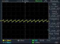
Negative Rail (DS0036):
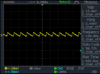
Positive Rail (DS0037):
Phrack! Why aren't my pictures displyaying instead of just showing as attachments now?
(I left Voltage set at 20mV instead of 10mV like I did with the last traces, so don't compare
them directly).
Traced both sides on Channel 1 of the scope.
Negative Rail (DS0036):
Positive Rail (DS0037):
Phrack! Why aren't my pictures displyaying instead of just showing as attachments now?
Attachments
Last edited:
 Because they are BMP format. You want JPG or PNG for images. I've added them to your post.
Those look OK. The short downward part of the trace is the charging cycle and the longer slope is the discharging cycle. The second image is the same, a short upward charge to the peak AC voltage and then a gradual discharge until the incoming AC charges the cap again.
Mooly:
That was very kind/generous of you. Why not BMP? It's listed as a valid file format in the upload dialog box.
So, these scope readings stand okay as is? Isn't 11.2mV a bit too high for ripple?
Also, does that suggest Channel 2 of the scope isn't reading properly? I already had to replace the stock probe when I got the unit-it broke. Now I wonder about this one.
Its valid in as much as it attaches OK, it just doesn't display as an image.
To prove the scope, simply duplicate the test using channel 2. The readings should be identical. If you use the scope in dual trace mode and keep the v/div and AC/DC coupling the same for both then the two traces should be identical and overlay each other.
11.2mv doesn't sound very much tbh. What is there connected across the rail to draw current ?
I just disappeared with the above post in limbo while you posted.
Nothing attached should really give pretty much no ripple at all, but the fact its so small doesn't really suggest a problem, perhaps more some measurement artefact with the set up.
If you do a listening test then remember to discharge the caps before coupling up to the amp and I would also recommend you use a bulb tester initially (before connecting speakers etc), just to check all is well and that there is no DC offset.
Bleeders will help speed up the discharge time.Thanks Mooly. Will do. I'm busy for a few days, but should get to it soon. The Chipamp power supplies feature bleeder resistors on the bottom. I assume those would discharge the caps in a short time?
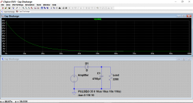
You can estimate the time from the RC time constant.
Suppose you have 4700uF of smoothing capacitance on the supply rail. C=0.0047F
You have fitted a 2k2 resistor as the bleeder of a 35V supply rail.
Dissipation is 35²/2200 = 0.557W. A bit too hot for a 600mW resistor use 1W or 2W.
The RC time constant is 0.0047F * 2200ohms = 10.34seconds.
The capacitor will discharge by ~63% in ~10seconds. in roughly 5times RC the cap will have discharged to <5% of it's starting voltage, i.e in about a minute the cap will be down to ~1½Vdc
I was commenting in another Thread over the past few days where this same question came up, so last night I measured my amplifier. It has no bleeders and uses ±45mF on ±50Vdc supply rails. I switched off and measured the voltage on the cap, it was reading 2.8Vdc and the elapsed time was about 12seconds since this was on my workbench with the lid off and the meter to hand. What good would adding a bleeder to that discharge time? If it was a ClassA amplifier, then it would be even quicker.
Now to the next part. Does the bleeder have any effect on ripple voltage?
Most EF output stages operate with between 20mA and 150mA of output bias current. That causes ripple on the supply rails. The amplifiers PSRR has to attenuate that ripple sufficiently to become inaudible and preferably below measurement threshold of a 199.9mVdc setting on a DMM. Adding extra ripple due to a bleeder has less effect, but it's still measurable. In ClassA it is probably not measurable.
However many CFP output stage power amplifiers draw between 5mA and 25mA of bias current in the quiescent condition. Add on an allowance of 10mA to 20mA for the front end and you have a total ripple inducing current draw of 15mA to 45mA
A bleeder that draws the same current would double the ripple voltage, i.e. increase ripple by 6dB.
That requires the amplifier PSRR to be better by ~ 6dB, than the EF style to make the hum at the output match when no bleeder is adopted.
The effect of adding a bleeder is in my view more significant in adding to supply rail ripple and risk of output hum, than it has on quickly reducing supply rail voltage.
Many don't like this interpretation. Why should I argue with Builders that have already made up their minds?
State the facts and let the Builder choose his/her poison.
Last edited:
You want bleeder resistors. Otherwise the caps can stay charged for quite a while after you turn off the circuit. That's not a good practice. I usually have 1-10 mA flowing in the bleeders.
I'm not sure what your concern is. It looks like the DC voltage is about ±28 V which is perfect for an LM3886-based amp. The few 10s of mV of ripple is nothing to be concerned about.
Tom
I'm not sure what your concern is. It looks like the DC voltage is about ±28 V which is perfect for an LM3886-based amp. The few 10s of mV of ripple is nothing to be concerned about.
Tom
- Status
- This old topic is closed. If you want to reopen this topic, contact a moderator using the "Report Post" button.
- Home
- Amplifiers
- Chip Amps
- Diagnosing Chipamp.com PSU problem