Reference my project of 5.1 system located at http://www.diyaudio.com/forums/showthread.php?s=&threadid=29646
I want to use digital pots with the system Chips like DS1802, DS1806,TDA7448 or DS1666 I find that except DS1802 and DS1666 I need a microcontroller with these chips, jus what are these microcontrollers like I2C bus, where can I get them and how can a build a volume control around a microcontroller.
Any help will be appreciated.
If you want to program a microcontroller to controll a digital volume control. I suggest you use an Atmel AVR microcontroller, and use the Bascom AVR compiler. The Bascom AVR compiler is easy to work with.
I also suggest you to use something like PGA2310, WM8816 as I believe that these are better.
/Freddie
I also suggest you to use something like PGA2310, WM8816 as I believe that these are better.
/Freddie
I've recently completed a 5.1 system using three PGA2310 digital pots from Burr-Brown. These use the three wire SPI connection to adjust the volume - data, clock and chip select, where DATA is two 8-bit numbers to set the volume of the left and right outputs.
The following link shows an oscilloscope screen with the relationship of the three signals:
http://www.diyaudio.com/forums/showthread.php?threadid=24731
Edit: for clarification, signal 1 is chip select, 2 is data and 3 is clock.
A microcontroller is a microprocessor with additional functions added which make it easier to use in embeded systems (as opposed to a computer). They usually have internal SPI, I2C drivers or general purpose IO pins that you can use for these functions. I used a CPLD to control the three PGA2310s but I wouldn't recommend this method to a beginner.
I2C is a two wire signal protocol. A web search should throw up plenty of links explaining more about this.
Nice one,
David.
having seen your thread I would be very much interetsed in building one for myself except that in the poweramp section I would be using LM3886 rather than anything else could you plz post schematics of your 5.1 system, and PCB as well if u don't have any problems..
However for the microcontroller thingy I would need some more clarification..
However for the microcontroller thingy I would need some more clarification..
I plan on getting into the Microchip brand PIC's. The chips are only a ~$4 each and you can program them using Basic, which is pretty easy to understand. There are other languages too, but I like Basic, its easy to understand, and has plenty of capability for basic audio requirments.
You can even get the chips free with samples from Microchip, plus all the software is available for free. However the hardest part is getting the programer. Luckily I was able to get a DIY programmer from a local shop for $15, but I have yet to put it together. It uses a parrellel port on the computer.
This is one of the good sites for learning how to program in Basic on a PIC. MicroEngineering Labs. Here everything you need to get started.
I made my pic programmer for about 5€
http://www.sprut.de/electronic/pic/projekte/brenner5/
and use a 16F628 with internal clk for minimal parts with PGA2310 (11)
http://home.tu-clausthal.de/~tpa/PGA/index.html
http://www.sprut.de/electronic/pic/projekte/brenner5/
and use a 16F628 with internal clk for minimal parts with PGA2310 (11)
http://home.tu-clausthal.de/~tpa/PGA/index.html
Abidr,
This is the schematic of the volume control section. It's fairly straight forward but a few notes on some of the other signals may help your understanding. The POWER_GOOD and RELAY_DRIVE signals sense the amp powering up and connect the speakers (via relays) after a two second delay. The up/down switch and a power-on LED are connected to J23 while J22 is used for programming the CPLD (U17). The CPLD is clocked at 4MHz by U18.
Email me if you would like the whole eight page set. Alternatively, if you prefer the schematic and layout files then I suggest you download a demo copy of the Proteus 6 software from...
Http://www.labcenter.co.uk
The demo isn't time-limited but the save and print functions have been disabled. It's a 15MB download. The schematics are 180K and the layout is 200K.
Nice one,
David.
Attachments
Hi all!
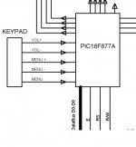
I have also DIY 6-channel preamp controlled by PIC16F877A.
u can find microcontroller schematic here: http://ktwww.pspt.fi/w9042/uc_sch.jpg
and picture of my prototype: http://ktwww.pspt.fi/w9042/102_0263.jpg
Sorry, picture size is big (1MB and 0,6MB). I hope that u can get some ideas for your preamp. I think that it is very ambitious project to build DIY 6-channel preamp, and when its working u go in heaven") (I hope u understand what i mean)
(I hope u understand what i mean)
I have also DIY 6-channel preamp controlled by PIC16F877A.
u can find microcontroller schematic here: http://ktwww.pspt.fi/w9042/uc_sch.jpg
and picture of my prototype: http://ktwww.pspt.fi/w9042/102_0263.jpg
Sorry, picture size is big (1MB and 0,6MB). I hope that u can get some ideas for your preamp. I think that it is very ambitious project to build DIY 6-channel preamp, and when its working u go in heaven
(I hope u understand what i mean)Thanks Guys
Well I'm back after a whole week of travelling (being sales manager u have got to do it) I have gone through your posts guys and I really appreciate the quality of posts at DIY,
What I really intend to do is first make 5.1 pre with microcontroller and then maybe a 5.1dolby decoder, I am in the process of finding couple of chips lets see how far it could go, or alternatively may be a Qsound processor from stereo input to 5.1 out could be another project..
I ll definitely need u guys to help me out.
Well I'm back after a whole week of travelling (being sales manager u have got to do it) I have gone through your posts guys and I really appreciate the quality of posts at DIY,
I would really appreciate if you could email me whole 8 pages, I ll download the software mentione, however I personally use circuit maker 2000, and proteldx both are full working programmes.daatkins
What I really intend to do is first make 5.1 pre with microcontroller and then maybe a 5.1dolby decoder, I am in the process of finding couple of chips lets see how far it could go, or alternatively may be a Qsound processor from stereo input to 5.1 out could be another project..
I ll definitely need u guys to help me out.
MIKA:
I have downloaded your pics and they seem alright, however I would be more interested in PCB designs and software routines maybe,
I went out to local electronics market and purchased this LCD matrix having number WM-C1602N, anyone havinh any idea where I could get its datasheets..
I have downloaded your pics and they seem alright, however I would be more interested in PCB designs and software routines maybe,
I went out to local electronics market and purchased this LCD matrix having number WM-C1602N, anyone havinh any idea where I could get its datasheets..
PIC16877
Having done all the parts search on microcontrollers and pots, I found PIC16F877 at one of the shops pretty cheap around 6 dollars however, theres a catch 4 MHZ chips and 20 MHZ chip, price differnce is like 50 cents, anyidea what chips should be used 4 mhz or 20 mhz with the digital pots..
Having done all the parts search on microcontrollers and pots, I found PIC16F877 at one of the shops pretty cheap around 6 dollars however, theres a catch 4 MHZ chips and 20 MHZ chip, price differnce is like 50 cents, anyidea what chips should be used 4 mhz or 20 mhz with the digital pots..
Hi!
Im not 100% sure, but i would use 4MHz chip, because i think it is best way to use lowest possible clock frequency. Lowering clock freq will lower disturbances which are coming from CPU clock. If u are going to use clock at 20MHz freq, u really have to make good 2 layer (at minimum ) PCB etc.
Im not 100% sure, but i would use 4MHz chip, because i think it is best way to use lowest possible clock frequency. Lowering clock freq will lower disturbances which are coming from CPU clock. If u are going to use clock at 20MHz freq, u really have to make good 2 layer (at minimum ) PCB etc.
The 20 MHz type works with 4MHz also. Both also work with less, if you want use a clock crystal 32,7kHz. I have not problem using them with 20 MHz on a single sided prototyping board without any groundplane. In my experience they also have no problem to stop when pulling the crystal and start running again when pluged in back. (for those who prefer a really slow clock)
(PS, currently i´m working together with another member on an 16F877 based system with PGA, LCD,relais input selector, and option for future upgrade IR remote)
(PS, currently i´m working together with another member on an 16F877 based system with PGA, LCD,relais input selector, and option for future upgrade IR remote)
well so far so good, having procured PIC controller its about time to get started with programming the chips with a DIY programmer found at http://www.angelfire.com/ok3/masterbyte/ and what help could DIY community extend in understanding the programmer, first secondly what subroutines are required with attached configuration..
Help wanted desperately..
Help wanted desperately..
Attachments
Assembler or C/Basic whatever?
(i use assmbler)
There are more than one way. Loop, looking what key is pressed. In case key is pressed something happens.
sleep, wake up on interrupt some key is pressed --> something happens. when done sleep again. you need to use PortB for this.
sleep, timer interrupt, on interrup test if any key pressed --> something happen, else sleep.
In case sopmething happens: look is key pressed new or since last time noch change. If it was pressed last time do nothing. If it changed from not pressed count up/down value (menue item or volume) and transfer new value to PGA/ digital pot
i would not use switches but rotary encoder. If you use PGA its a simple task to transfer my 16F628 code to the 877 for a start.
thanks for your reply, rotary encoders cannot be found in Pakistan except that I junk a sony VCR and get it out of there, as for choices what i want to do is put a 20x2 LCD three CS3310/WM8816/PGA2310 whichever I could find here easily, use key pad with menu like front(L+R) Volume Up/down, Rear (L+R) Volume up/Down, Center Volume up/down, Sub woofer Voluem up/down.
If you could send in s/routines for PGA2310 that 'd be good for a start, but what programmer I mean for PIC u use and what the software?
If you could send in s/routines for PGA2310 that 'd be good for a start, but what programmer I mean for PIC u use and what the software?
- Status
- This old topic is closed. If you want to reopen this topic, contact a moderator using the "Report Post" button.
- Home
- Amplifiers
- Chip Amps
- Digital Pots in 5.1 System