TDA729x also means millions of breaking-prone amplifiers built within a cat's lifetime.
Yeah, they tend to explode now and then on themselves.


I am a Crazy Gool. These chips have over-current and -heating protection and are quite HF-stable. Yet the internet is littered with reports of them failing. Usually a part of the die explodes and shoots off a part of the plastic enclosure. Why?
I know the reason but am not in need to prove it. I think, the men designing a MOSFET power amplifier IC for the digital age treated Standby as make-no-mistake power-good. The men writing the datasheet did not know or feel pressed to tell this. The men applying these ICs hid their heads in the sand.
Here is my schematic:
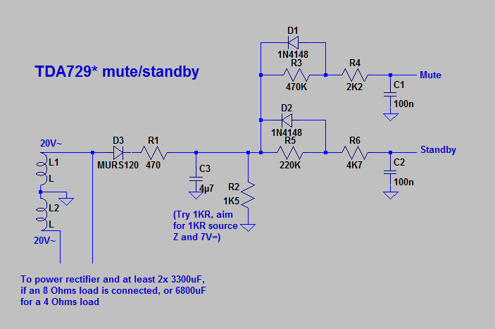
At mains switch on, it outputs a modest pulse. At mains switch off, it goes silent immediately.
I know the reason but am not in need to prove it. I think, the men designing a MOSFET power amplifier IC for the digital age treated Standby as make-no-mistake power-good. The men writing the datasheet did not know or feel pressed to tell this. The men applying these ICs hid their heads in the sand.
Here is my schematic:
At mains switch on, it outputs a modest pulse. At mains switch off, it goes silent immediately.
Attachments
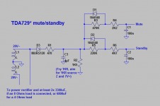
Correction: R1=R2=1KOhms, C3=22uF. Also, 2x 3300uF main capacitors is borderline small: Altho this has best sound, gradually starting to modulate instead of just clipping, it reduces reliability. This bass combo will rattle, so any big parts i add i must sturdily fix. Also when enlarging capacitors i had to strengthen rectifier. Too lazy for all that fuzz. Built in is a nice Celestion Truevox 1215.
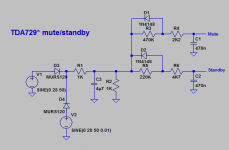
No, C3=4.7uF, but turn the auxiliary rectifier into a symmetric one by having another 1N4004 fetch the negative swing from the other half of the transformer secondary. C1=C2=470nF.C3=22uF.
Attachments
Last edited:
I would think they did know and did tell us. Look at Fig.5 in the 7293 datasheet. From that it should have been always clear to anyone that, timing-wise, MUTE must be bracketed by STANDBY must be bracketed by the supply which should ramp up/down symmetrically (with respect from STBY-GND and SGND pins). Maybe they should have written "mandatory" instead of "suggested" in the caption of Fig.5 to be more clear.I think, the men designing a MOSFET power amplifier IC for the digital age treated Standby as make-no-mistake power-good. The men writing the datasheet did not know or feel pressed to tell this.
They printed an application circuit, which does not really chase this procedure. There, shortest time constant is 10KOhms*10uFarad=100ms. On top of that, they allow Mute and Standby signals to have rail voltage, hence after mains switch-off it may take much longer than 100ms, until Mute becomes less than 2.5V and goes LO. Now if there is a large signal, while mains is switched off, power capacitors decharge soon, or if mains is toggled, the Matruschka breaks.
To clarify:
The result is, that, if mains is switched off, while a large audio signal is put out, then Standby might be still HI (chip logic considering the amplifier being ON), while (particularily negative?) power supply goes OFF. This prolly causes the chip to break.
Datasheet for TDA7294V also shows an advanced amplifier with cascaded power supply, and TDA7293 output stages can be run in parallel, hence there might be still other reasons for explosive damage.
I see no sense in building anything on grounds of denial, KSTR, so i have to get this strait.
This is Standby time constant and were the same as 10 Ohms loudspeaker load times 10 mFarad power capacitor. Often, loudspeaker load and power capacitor have lower values, resulting in a shorter power supply time constant. Add, that power supply must be higher (10V) in order to count as HI than Standby (3.5V).There, shortest time constant is 10KOhms*10uFarad=100ms.
The result is, that, if mains is switched off, while a large audio signal is put out, then Standby might be still HI (chip logic considering the amplifier being ON), while (particularily negative?) power supply goes OFF. This prolly causes the chip to break.
Datasheet for TDA7294V also shows an advanced amplifier with cascaded power supply, and TDA7293 output stages can be run in parallel, hence there might be still other reasons for explosive damage.
I see no sense in building anything on grounds of denial, KSTR, so i have to get this strait.
- Status
- This old topic is closed. If you want to reopen this topic, contact a moderator using the "Report Post" button.
- Home
- Amplifiers
- Chip Amps
- flaws of some powerful chipamps