They are all op-amps somehow, since they have a non-inverting and an inverting input. Yet some of them do not integrate input protection diodes. As i wrote, this lack of input protection may be good for a comparator, for which the circuit designer will tailor input protection, but not for a linear amplifier.
Protection diodes are a good idea. I always include them in all my circuits.
They work like op amps of course but have application specific features. Their phase/bandwidth performance is poor for an op amp but they work great as power amplifiers.
In spite of their price, I don't think engineers use them in servo circuits. I think you could use them in some servo circuits, though.
Audio chip amps are assumed to be operated closed loop, and when the loop opens during clipping it is assumed the signal is low (2...3Vpeak or so) and that there is a source resistance in the low kOhm range at both input pins. Also, common mode operation point is assumed to be very close to 0.5* total supply.
An input protection and a large input common-mode range is therefore not deemed necessary for these specialized opamps.
An input protection and a large input common-mode range is therefore not deemed necessary for these specialized opamps.
Diode protection on the input ensures that the input coupling capacitor never causes the unit to latch up on power down. This is especially important when a single ended supply is used.
I use diode clamps on line level circuitry too. The diodes do nothing at all unless they're needed. They cost around 2 cents apiece if bought in bulk so the biggest cost is board space.
A couple of diodes and a resistor can provide virtually unimpeachable input circuitry protection. I don't see a downside to that.
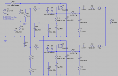
Here is a circuit, which likely breaks on power-up or -down, if there were no input protection diodes:

In a single-chip circuit, in which i accidently shortcutted the resistor of the 2R2/470nF network, another chip broke. In both cases only the differential-input stage broke, as fuses did not.
In a single-chip circuit, in which i accidently shortcutted the resistor of the 2R2/470nF network, another chip broke. In both cases only the differential-input stage broke, as fuses did not.
Attachments
Last edited:
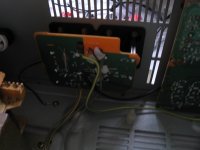
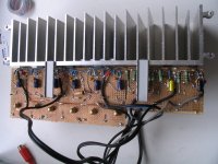
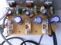
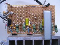
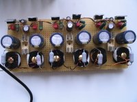
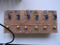
Thank thee, Daniel! I have to use the single rail supply, which i already have. I was worried, the nine chips could use too much idle power, heating up the cooler (9*50mA*46V=27W), but that is not the case at all; even if i cover the cooler for a while, it gets barely luke-warm. UTC state 30mA idle current but have prolly futher reduced it and shrunk the die. So it makes sense to build the circuit as small as possible, with feedback network and 100nF capacitors right at chip legs at board bottom. And use a single rail supply indeed, so the chips can be easily cooled without insulation, what also results in a low-resistance ground path, so i screwed loudspeakers ground to the cooler, too.
Attachments
Last edited:
The heat concerns are stability related. In my opinion, the datasheet sample schematics probably weren't operating a real speaker at high power; and, thereby, in real application, the stability slips up when used at high power, resulting in excessive heat, nonlinear output and severely diminished power output capacity.
So, I think that is the majority of the heat concerns.
A multi-tone, highly variable asymmetric signal (music) and a variable output load (speaker), are likely the real conditions, without sufficient commonality to the test conditions. Same schematic can't work equally well for both test and real uses, because they're different.
Then, the first thing to do is find out why it didn't work perfectly well and cool with a modest heatsink, a relevant input signal and a real speaker.
The odds are high and the means are present, that the datasheet's sample schematic has not provided adequacy for your application.
It's a bad circuit. Common mode and differential input range is violated during power-up and notably during power-down. TDA2050 input CM range isn't given, but when you pull an input higher that the supply no wonder the input stage breaks.Here is a circuit, which likely breaks on power-up or -down, if there were no input protection diodes
OR pitfalls of running op-amps on single supply
Thank thee. My amplifier has powered up good for a dozend times, bereason i built the 20V= offset generator with higher impedance than shown, namely 270KR, 220KR and 4uf7. I will not switch it on again before i have added the necessary diode.
Thank thee. My amplifier has powered up good for a dozend times, bereason i built the 20V= offset generator with higher impedance than shown, namely 270KR, 220KR and 4uf7. I will not switch it on again before i have added the necessary diode.
Strangely, the ST TDA2050 datasheet shows a single rail amplifier circuit but without a reverse diode preventing offset input voltage becoming much higher than supply rail on power-down.
Also, even with three protection diodes in place the amplifier might still die, namely if there occurs hi input voltage, say +-15V, on power-down. In order to prevent this, two additional reverse diodes must be layed between positive input, supply rail and ground.
Round up, bad-case (connecting a telephone line) DC protection of a single rail operational amplifier needs a 100V series input capacitor, a 2KR2/0.25W series resistor, four 1N4148 diodes and one 1N4148 or 1N4007.
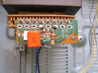
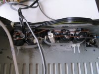
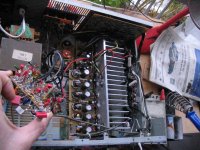
TDA729x also means millions of breaking-prone amplifiers built within a cat's lifetime. This is how I repaired one with TDA7294V:
Exchanged old chip, which had exploded, for new one and repaired burnt PCB trace. I left power supply untouched, altho main capacitors (2x 3300uF, for +-32V idle) are quite small. I changed Standby/Mute circuit in opinion, that nestled power-up and -down sequence as proposed in datasheet were a must, at least Standby must be Down while power is down. Datasheet-proposed application circuit does not follow this sequence, if the amplifier is driven hard while getting switched off. So, with some pre-work by Harley Benton, i thot up topology, levels and time constants. I have just switched it on and off sucessfully and will test it further tomorrow and, if it works out, and if there is interest, post a schematic.
Exchanged old chip, which had exploded, for new one and repaired burnt PCB trace. I left power supply untouched, altho main capacitors (2x 3300uF, for +-32V idle) are quite small. I changed Standby/Mute circuit in opinion, that nestled power-up and -down sequence as proposed in datasheet were a must, at least Standby must be Down while power is down. Datasheet-proposed application circuit does not follow this sequence, if the amplifier is driven hard while getting switched off. So, with some pre-work by Harley Benton, i thot up topology, levels and time constants. I have just switched it on and off sucessfully and will test it further tomorrow and, if it works out, and if there is interest, post a schematic.
Last edited:
- Status
- This old topic is closed. If you want to reopen this topic, contact a moderator using the "Report Post" button.
- Home
- Amplifiers
- Chip Amps
- flaws of some powerful chipamps