Just my opinion.
TDA2050 seems to be a chip of lo distortion, hi efficiency and hi reliability, if maximum output is limited to 25 Watts. But i need more power from one output.
I read German stories of TDA729* becoming damaged, if Vdd is missing, while Vcc is up, say if chip pins "signal ground" and "standby/mute ground" become lowest chip potential. If this is really so, this is a huge flaw. (TDA7293 seems to be the most powerful but also critical one. For 7294V, 7295 and 7296 "standby/mute ground" is allowed to be Vdd.)
Edit: In an old DIYaudio discussion someone gives an explanation for TDA729* failure: Chip substrate must be most negative potential of the circuit, else it blows. Read that thread, if you intend to do cheap chip-amps.
Now the LM3886 looks more solid but has propagated some genes of the former. For one thing muting functionality, and it has a ground pin. An op-amp should have no ground pin.
A true bipolar op-amp has a maximum differential input voltage of +-2.5V, because inputs are connected to a differential amplifier, which consists of two equal transistors with common emitter, and BE junction must not exceed 5V for PNP and -5V for NPN. But datasheets for LM3886 and TDA7293/4 state much more.
LM3886 has emulated DMOS output stage of TDA7273/4 with large shunt resistors (0.45 Ohms). These resistors heat up the chip, when it is driving a heavy load into clipping, and reduce power. On the upside they limit current. So it comes to output protection:
Maybe one should leave protection to passive devices. Small signals can cause large signals but cannot protect from large signals. Large signals must run out of power.
A single rail amplifier with rail ripple shows unsymmetrical clipping, and I(U) functions are different for positive and negative output transistor. This is bad. On the upside, the output capacitor is a great protector, tho i have already seen a shorted electrolytic capacitor. A wire fuse may also be useful. Sure this does not help, when output is short-cut, as transistors cannot take hi currents at hi voltage.
So one could either use that large shunt resistors and that strong or many output transistors, that it can withstand a short-cut, until the wire fuse blows, or employ proper jacks and plugs. Those ones should withstand heavy pushing and pulling and seem better than Speakon. Edit: They are bad, as the plug will stick out much too far becoming a long lever.
This seems right.
Last edited:
So one would use foil capacitors, which do not drift as much as electrolytics, for the stby/mute section. And do not use fuses in the power supply rails but only in the mains and the loudspeaker circuits, for if negative rail fails, while positive one is still on, the chip blows.
I used UTC TDA2050 with 46V single rail supply and found that i must lay two 1N4148 diodes antiparallel to inputs, limiting differential input voltage. Tho the latter is stated as +-30V maximum, it is stressed too much within my unusual circuit and way.
Usual circuits and other op-amps should profit from these diodes, too, getting hier reliability. Only catch may be, that the diodes may cause some circuits to get stuck at positive or negative rail: Input stage would not blow, but output could not settle, as negative feedback would like to.
Even with chipamps still not everything has been said and done.
My library system has a Linn Majik and LK100 biamped driving Kelidh's. The Majik's horsepower is driven by a chipamp. The system is over 20 years old and still sounds wonderful.
The only flaw I can see with the chipamps is the absolute necessity that you get the heat sinking correct.
J
The only flaw I can see with the chipamps is the absolute necessity that you get the heat sinking correct.
J
The only flaw I can see with the chipamps is the absolute necessity that you get the heat sinking correct.
I know! The laws of physics are so inconvenient. Just say no to physics...

Tom
LM3886
[...]
A single rail amplifier with rail ripple shows unsymmetrical clipping
The LM3886 isn't a single rail amp. And why would you want symmetrical clipping? You DON'T want clipping AT ALL!
Playing troll again?
I know! The laws of physics are so inconvenient. Just say no to physics...
Tom
Fortunate to have a Grizzly mini-mill I took some 1/8" stock and fashioned a tortion bar to attach the chipamp to heatsink. Before I did this (when it was just screwed down), I could get the thing to thermally cycle. Not pleasant.
The Majik, which dates from the early 1990's, used a TDA1514.
Attachments
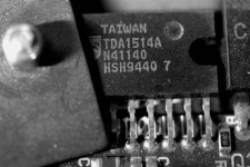
hmmm i can agree with the tda1514 needing some more heatsinking than expected.
that guy can get hot and has some problems with heat dispersion i guess.
used to have them, and love them.
it can deliver quality, i spent quite some hours polishing away the package to provide a better surface for the heatsink, and i used to sandwitch the chips between heatsinks.
made a world of difference, for some reason that thing is sensitive to heat as hell.
at one point i was close to smacking it with a water cooler to be honest.
it does a good job until you can keep it cold.
once it gets hot, the soun is medicore at best.
dynamics are lost as heat is gained.
anyone have a tip howcome? i'm usually not sensitive to stuff like that, i don't have that audiophool thing in my head at all. this is one of the few chips where i can sense a huuuge difference.
it does a good job until you can keep it cold.
once it gets hot, the soun is medicore at best.
dynamics are lost as heat is gained.
You have to invest a few sous in Bob Cordell's book "Designing Audio Power Amplifiers". Worth every centime.
> A true bipolar op-amp has a maximum differential input voltage of +-2.5V, because inputs are connected to a differential amplifier, which consists of two equal transistors with common emitter, and BE junction must not exceed 5V for PNP and -5V for NPN. But datasheets for LM3886 and TDA7293/4 state much more.
IF the limit were 5V, then the max diff would be +/-5V (not +/-2.5V).
The "limit" is really closer to 7V, but I agree with not pushing it because device damage increases hiss.
This "limit" is really for "optimum Silicon doping". If you want excellent hFE, and have no other constraints, the emitter junction breakdown will come to about 7V. Old-old Germanium devices were often symmetrical: 30V on both junctions. Lateral PNPs on basic planar integrated circuits are far from optimum dope, and one good side-effect is high emitter breakdown (because it is really doped to be a Collector of an NPN).
> leave protection to passive devices
Power-absorbing (wasting) resistors? Non-linear fuses which the user will replace with tin-foil?
It takes clever, even severe, protection to get 60+ Watts out of one bit of Silicon, and also keep total product cost down.
> employ proper jacks and plugs.
Wires run under rugs and furniture can short-out. Connectors on backs of speakers short out. In general, equipment designers pick lower-cost connections. Speakons etc will never catch-on outside the professional field.
> LM3886 ....output protection:
Yes, the '3886 can do some horrible things when pushed to the limits. But chipmakers have to design for millions of sales to cover their up-front costs. '3886 was not designed for the fussy members of DIYaudio, but for the millions of surround-sound systems sold to the general public. They serve very well in that application. The fact that a coddled '3886 can also be a very good HI-FI amplifier is a bonus for us. The fact that it does not cover ALL cases leaves room for us to play with many-device amplifiers to over-kill our problems.
> with chipamps still not everything has been said and done.
That could be true. But for large-production applications, Class D has massive advantages. I doubt any chip-maker will begin another large linear power amplifier in this market. Not enough potential sales.
Perhaps we should avoid combining all of online lore available into one amplifier; because, such a combination could hinder efficiency?I can confirm the 7293 will light on fire if you don't follow the spec sheet mute/stby wiring. It doesn't explain why they use the parts how they do and why, but unless you like flames you should follow it.
Talk about overkillSo one would use foil capacitors, which do not drift as much as electrolytics, for the stby/mute section. .
The much feared electrolytic value drift (or are you talking tolerance?) is still way smaller than anything which could cause trouble here.
Some TDA7293/4/5/6s blow up together with their stby/mute capacitors. One blow-up was traced to missing negative rail. OSdestroyer traced one to the stby/mute. There is something wrong in the state of Denmark.
LM3886 is prolly better but still not as reliable as it could simply be. I proposed to protect input stage by adding two small diodes. Can you comment on that, founded on your experiences?
In the Revox A78 signal transistors are not diode-protected, and at least in my built +18V supply voltage rang on switching on or off, causing too hi BE voltage, so burst noise appeared.
Protection diodes should be present, unless
* there are no external inputs, and supply voltage is at most a few Volts and guaranteed to not ring (by adding a power diode shortcutting any negative and a resistor-zener combination limiting positive supply voltage)
* or all input voltages, even internal ones (count any transistor base as input, unless you know better) are guaranteed harmless, and supply voltage guaranteed to not ring.
With comparator ICs there is a design dilemma; either good input protection or hi switching speed and hi input resistance. But if designers of linear audio circuits needing negative feedback anyway do not add protection diodes yet state +-30V maximum differential input voltage anyway, then well, i do not get it. Who pays me 198 cents for two blown TDA2050 ICs?
See Black Devil Improved post 7; give the amplifier positive output resistance, which limits shortcut current. Now fuses should not blow that often, that users start to replace them by tin-foil.
Is this a remote war, in which i have to fight men of my own nation?
LM3886 is prolly better but still not as reliable as it could simply be. I proposed to protect input stage by adding two small diodes. Can you comment on that, founded on your experiences?
In the Revox A78 signal transistors are not diode-protected, and at least in my built +18V supply voltage rang on switching on or off, causing too hi BE voltage, so burst noise appeared.
Protection diodes should be present, unless
* there are no external inputs, and supply voltage is at most a few Volts and guaranteed to not ring (by adding a power diode shortcutting any negative and a resistor-zener combination limiting positive supply voltage)
* or all input voltages, even internal ones (count any transistor base as input, unless you know better) are guaranteed harmless, and supply voltage guaranteed to not ring.
With comparator ICs there is a design dilemma; either good input protection or hi switching speed and hi input resistance. But if designers of linear audio circuits needing negative feedback anyway do not add protection diodes yet state +-30V maximum differential input voltage anyway, then well, i do not get it. Who pays me 198 cents for two blown TDA2050 ICs?
Power-absorbing (wasting) resistors? Non-linear fuses which the user will replace with tin-foil?
See Black Devil Improved post 7; give the amplifier positive output resistance, which limits shortcut current. Now fuses should not blow that often, that users start to replace them by tin-foil.
Is this a remote war, in which i have to fight men of my own nation?
Last edited:
Can´t you get a more modern and relevant example?In the Revox A78 signal transistors are not diode-protected,
That circuit is 40 or 50 years old
Not sure what datasheet are you looking at, but the SGS Thompson one I´m looking at states +/-15V ... whichb reaqds as "15V either way", not "15+15V=30V" as you seem to assume.do not add protection diodes yet state +-30V maximum differential input voltage anyway, then well, i do not get it. Who pays me 198 cents for two blown TDA2050 ICs?
And 15V peak is quite consistent with the roughly 7V per BE junction estimated by PRR .
And even so, damage will be nil if current is limited by a series resistor.
Even after 50 years still the same mistakes are maDe.
+- meaning "either way", wEll maybe, thanks! But datasheets of some bipolar opamps state a maximum differeNtial input voltage of only +-2.5V. I know also from first-hand experience, that 7V is too much for a BE junction.
In my circuits input currents Are Limited, positive input by 22KOhms DC and 2K2 AC, and negative one by the standard 22K/680 feedback network. Yet input stages broke.
These chips are purpose built for industry. They are ubiquitous in consumer products. They were not designed to be high power op amps. You can actually buy high power op amps and they cost a lot more than the LM and TDA series audio amplifier chips.
They're affordable, simple to use, and respond very well to all the gilding the lily (or polishing the turd) stuff we like to do here. They're so easy and cheap to use that a DIYer is virtually obliged to do something with them.
But maybe you should buy a couple of those power op amps (which are really designed for use in industrial servo systems) and see what you get. Some of them work with higher voltages. I bet you could make a nice power amplifier out of some of them, but they sure are expensive.
- Status
- This old topic is closed. If you want to reopen this topic, contact a moderator using the "Report Post" button.
- Home
- Amplifiers
- Chip Amps
- flaws of some powerful chipamps