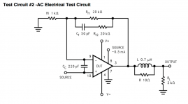
I'm trying to develop a mathematical justification for the values of all of the components I'll be using in my amp build. I have most of the other parts of the circuit figured out, but now I'm trying to calculate values for Cf and Rf2 (from the datasheet). The formula for calculating the Fc of the negative feedback low pass filter on page 8 in the LM3886 TI datasheet says:
fc= [Rf1*Rf2*(s+1/Rf2*Cf)]/[(Rf1+Rf2)*(s+1/Cf(Rf1+Rf2))]
My question is, what is "s" referring to?
Also, what's a good Fc to aim for here, and why?
fc= [Rf1*Rf2*(s+1/Rf2*Cf)]/[(Rf1+Rf2)*(s+1/Cf(Rf1+Rf2))]
My question is, what is "s" referring to?
Also, what's a good Fc to aim for here, and why?
s is complex frequency. s = j*omega. Further explanation (or perhaps confusion) is available here: https://en.wikipedia.org/wiki/S-plane
I'd stick with the values in the data sheet if I were in your shoes.
Tom
I'd stick with the values in the data sheet if I were in your shoes.
Tom
s is complex frequency. s = j*omega. Further explanation (or perhaps confusion) is available here: https://en.wikipedia.org/wiki/S-plane
I'd stick with the values in the data sheet if I were in your shoes.
Tom
Yes that does look complicated. I wonder if the calculation for Fc could be roughly approximated using
Fc= 1/2*Pi*Cf*Rf1
or
Fc =1/2*Pi*Cf*Rf2
Actually, now that I take a second look, I'm not sure what s is really... I'd probably have to derive the equation to find out. Given that fc is on the left, s = complex frequency doesn't really make sense.
To find fc, I'd run a simulation. Just set it up in TINA-TI (free from TI). You'll probably find a -3 dB frequency around 85-100 kHz. You don't really want it lower than that as that'll result in excessive phase at 20 kHz. Some argue that the upper -3 dB frequency of an amp should be >200 kHz.
Do beware that tweaking the gain or corner frequency will require re-tweaking of Rf2, Cf, and Cc.
Tom
Actually, now that I take a second look, I'm not sure what s is really... I'd probably have to derive the equation to find out. Given that fc is on the left, s = complex frequency doesn't really make sense.
To find fc, I'd run a simulation. Just set it up in TINA-TI (free from TI). You'll probably find a -3 dB frequency around 85-100 kHz. You don't really want it lower than that as that'll result in excessive phase at 20 kHz. Some argue that the upper -3 dB frequency of an amp should be >200 kHz.
Do beware that tweaking the gain or corner frequency will require re-tweaking of Rf2, Cf, and Cc.
Tom
No, you were right... After some google searching that went way over my head way too quickly, I discovered that s is the complex frequency, j*omega. In my searching, I read somewhere that a pure sine wave has an s of zero, so as an approximation I tried calculating the Fc with s=0, but the result was much too low to be real, so no luck there...
Then I found this article, which I think said the low pass Fc could be found with Fc=1/2*Pi*Rf1*Cf
Is there any reason why the latter approach wouldn't work for a rough estimate?
Rf1 is in parallel with Rf2 + Cf. That changes things. The overall gain in non-inverting configuration is: Av = 1 + Zf/Zgnd, where Zf is the impedance from the output of the LM3886 to the inverting input (that'd be Rf1 || (Rf2+Cf)) and Zgnd is the impedance from the inverting input to ground. This calculation ignores any effect of Cc.
Zf(s) = Rf1 * (Rf2 + 1/sCf) / (Rf1 + Rf2 + 1/sCf)
Go from there...
What are you trying to do? Do you need a certain corner frequency? If so, you're better off setting it with an RC on the input to the amp as this makes the corner frequency dependent on RCs (which can be purchased at very tight tolerances) rather than the characteristics of the LM3886 which result from production tolerances and aren't all that tight.
If you want the widest bandwidth possible, use the values shown in the data sheet.
Tom
(Hz).
The hf corner frequency is nearly equal to 1/(2Pi*RC), where R is the feedback resistor,
and C is the capacitor across it.
The complex frequency s = (sigma + j*omega), where omega gives the steady state behavior,
and sigma gives the transient behavior. You set sigma to zero for the steady state response,
and then s = j*omega. Calculating the magnitude of the response by done by taking the sqrt
of the resulting formula times its complex conjugate (where all j are replaced with -j),
which is always a real number.
The corner frequency has to be of the form 1/(2Pi*RC) for consistent units.
Since R*C has units of seconds, then 1/(2PI*RC) has units of cycles/second, or frequency (Hz).
The factor of 2Pi converts radians to degrees, since there are 2Pi radians in 360 degrees (one cycle).
I read somewhere that a pure sine wave has an s of zero, so as an approximation I tried calculating
the Fc with s=0, but the result was much too low to be real, so no luck there...
Then I found this article, which I think said the low pass Fc could be found with Fc=1/2*Pi*Rf1*Cf.
The hf corner frequency is nearly equal to 1/(2Pi*RC), where R is the feedback resistor,
and C is the capacitor across it.
The complex frequency s = (sigma + j*omega), where omega gives the steady state behavior,
and sigma gives the transient behavior. You set sigma to zero for the steady state response,
and then s = j*omega. Calculating the magnitude of the response by done by taking the sqrt
of the resulting formula times its complex conjugate (where all j are replaced with -j),
which is always a real number.
The corner frequency has to be of the form 1/(2Pi*RC) for consistent units.
Since R*C has units of seconds, then 1/(2PI*RC) has units of cycles/second, or frequency (Hz).
The factor of 2Pi converts radians to degrees, since there are 2Pi radians in 360 degrees (one cycle).
Last edited:
The hf corner frequency is nearly equal to 1/(2Pi*RC), where R is the feedback resistor,
and C is the capacitor across it.
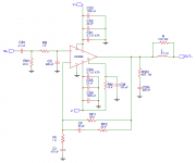
For a simple RC, yes. For the circuit OP is asking about, no. Schematic attached.
Tom
Attachments
At 160 KHz this filter turns phase of closed loop gain by Pi/4. This is done in order to mimik open loop gain, which also has a lowpass starting at this frequency. Since open loop gain already has another lowpass, the dominant one, starting around 1 KHz, open loop phase at 160 KHz is 3Pi/4. If phase between open and closed loop gain became Pi, the amplifier would resonate, or even oscillate, if closed loop gain was 1 or bigger. That filter shall dampen resonance.
Still i do not think, that it is a good idea. Just solder ceramic 10nF capacitors parallel to all electrolytic capacitors on bottom side, use recommended layout and all proposed high-frequency stabilizers except for that feedback filter.
Still i do not think, that it is a good idea. Just solder ceramic 10nF capacitors parallel to all electrolytic capacitors on bottom side, use recommended layout and all proposed high-frequency stabilizers except for that feedback filter.
Grasso, you're missing the point.
As the output swings near the negative rail voltage, the VAS stage in the LM3886 starts to saturate and the gain plunges. This causes the loop gain to drop. In most LM3886-based circuits, this results in some spurious oscillations as the output swings negative. To combat this, Cc is introduced. The drawback is that Cc causes some overshoot on the transient response. This is dealt with by introducing Rf2 and Cf. If you tune the circuit right, you can get an amp that can be driven cleanly to clipping and has a well-controlled transient behaviour.
You are right that to get good performance, you need good decoupling. That's a separate issue, though.
Tom
Zf(s) = Rf1 * (Rf2 + 1/sCf) / (Rf1 + Rf2 + 1/sCf)
This may be a stupid question, but is that "Zf as a function of s"? So I could use this equation to find s, then plug it into the Fc formula in the datasheet?
What are you trying to do? ... If you want the widest bandwidth possible, use the values shown in the data sheet.
Tom
I will be using the values in the datasheet (Cf=50pF; Rf2=20K), but I wanted to find the cutoff frequencies of all the different filters in the circuit. Mostly just out of curiosity but also to better understand how the circuit works.
As I understand it, Cf and Rf2 set the frequency that determines the upper limit of the amp's bandwidth. Or am I way off there?
the extra parallel Rf2 + Cf adds in a pole zero to the frequency response.
Consider first the case of Rf1 as nfb alone.
You can see the closed loop gain.
Now add in the extra Rf2, but assume that Cf is a zero ohms impedance.
You now have a lower gain because the total feedback resistance is lower.
The frequency that Cf starts to have a big effect is predicted by looking at the Rf2 & Cf turn over frequency, i.e use Freq = 1/{2piRC} to find the frequency where Rf2 = Impedance of Cf.
This is confused by the extra Cc, since that operates as a capacitive voltage divider
Use that to analyse it more thoroughly in a simulator.
Sim the simplest with Cc and Rf2 and Cf all omitted.
Add in Rf2 and sim again. See what changes and what frequcnies over which it changes.
Add in Rf2+Cf and sim again. see the changes.
Add in Cc alone and sim again.
Finally add in Cc Rf2 & Cf and sim again.
You will find that these three extra components cause an interaction that is not replicated by looking at any single component. That's the power of the simulator. It allows you to ask the right questions AFTER you have started to understand what is happening.
If you don't know the questions to ask the simulator, then you can't make sense of the answers.
Last edited:
Not really. What those extra components are doing is modifying the stability margins by changing the open loop gain at various ranges of frequencies.As I understand it, Cf and Rf2 set the frequency that determines the upper limit of the amp's bandwidth. Or am I way off there?
When the correct combination has been arrived at you have a stable amplifier.
Only after that has been determined do you add the input filters to set the system bandwidth.
The two input filters ensure you don't feed in signals that the amplifier can't handle and thus misbehave.
Not really. What those extra components are doing is modifying the stability margins by changing the open loop gain at various ranges of frequencies.
When the correct combination has been arrived at you have a stable amplifier.
Only after that has been determined do you add the input filters to set the system bandwidth.
The two input filters ensure you don't feed in signals that the amplifier can't handle and thus misbehave.
I see... So the lower bandwidth limit should be set by Cin and Rin. Would the upper bandwidth limit be set by Rb and Cc then?
Attachments
add an RF filter using a series resistor and a shunting capacitor
I guess my question now is... Is the RF filter you speak of acting as an upper bandwidth limiting filter? I have 1K (Rb) in series with the input, and a 680 pF cap to ground (Cc).
So if I'm not mistaken, the upper -3db point should be
Fc= 1/2*Pi*Rb*Cc
=234 kHz
With a Cin of 4.7 uF and Rin of 20K, the lower -3db should be
Fc= 1/2*Pi*Rin*Cin
= 1.69 Hz
Am I getting this right?
My Ci is 470 uF, so the lower Fc of the feedback loop (0.34 Hz) is ~5 times below the input lower Fc. Still not sure what the upper Fc of my feedback loop is though.
Last edited:
Cc is not connected to Signal return. it is across the -IN & +IN inputs.
You have shown a 680pF connected to power ground. That should be either to signal return, or to -IN.
Sorry, I guess I should have been more clear in the schematic. On my PCB layout I have Rin, Cc (680 pF), Ci, and Ri connected to a signal ground plane, and everything else connected to a power ground plane. Input ground and speaker ground are routed separately to the main ground, off of the PCB...
I have read multiple comments where you and others suggest that Cc should not be connected to IN -, but should be connected to ground... Is that not the best arrangement?
Also, do the values of Rb and Cc determine the upper -3db cut off that set the upper range of the amplifiers bandwidth?
In general attaching capacitance to -IN can make an amplifier unstable.
But for a circuit Designer who knows how to work out the ratios of Cf and Cc, they can use Cc to improve stability. There are a couple of papers on this, but it's a bit deep for me. That is what Tomchr has done for you. Copy it, if you can't do it yourself.
But for a circuit Designer who knows how to work out the ratios of Cf and Cc, they can use Cc to improve stability. There are a couple of papers on this, but it's a bit deep for me. That is what Tomchr has done for you. Copy it, if you can't do it yourself.
In general I agree that adding a cap across the inputs of an opamp is not recommended. In case of the LM3886 it is actually needed for stability as the output swings towards the negative rail.
Cc goes from the non-inverting input to the virtual ground at the inverting input. As long as the amp has sufficient loop gain to make a good virtual ground, the equation in Post #16 should be pretty close to reality.
Andrew's analysis in Post #12 is a good one. Go piece by piece in the simulator and watch the frequency response change.
The reason for the complicated equation for the upper -3 dB frequency is that the poles and zeros set by Cc, Rf1, Rf2, Cf, and the loop gain of the amp fall fairly close to each other. They're all in the 100 kHz - 1 MHz range (AFAIR). That means you have to use the full math to get accurate results.
If the poles and zeros had been decades apart, they wouldn't interact (much), thus, the math can be simplified to treat one pole/zero at a time.
Tom
- Status
- This old topic is closed. If you want to reopen this topic, contact a moderator using the "Report Post" button.
- Home
- Amplifiers
- Chip Amps
- LM3886 - Calculating Fc for low pass NFB filter